Surge Protection Device

a protection device and surge technology, applied in the field of electronic circuits, can solve the problems of surges lasting longer than 1-msec, circuits are typically bulky, and surges are encountered in the event of surges, and achieve the effect of preventing damage to equipmen

Active Publication Date: 2008-08-14
BOURNS INC
View PDF3 Cites 37 Cited by
  • Summary
  • Abstract
  • Description
  • Claims
  • Application Information

AI Technical Summary

Benefits of technology

[0032]The apparatus can be conveniently provided as a single package circuit board mountable electronic circuit device.

Problems solved by technology

Such circuits are typically bulky and may have large associated capacitances which are undesirable.
Whilst the circuit of FIG. 1 is relatively quick-acting and overcomes the problems associated with the use of gas discharge tubes, problems are encountered in the event of the surge being sustained.
However, surges may last longer than 1-msec.
In that case circuit 2 would likely be destroyed whilst dissipating power associated with the surge in the form of heat.
The destruction of circuit 2 during a surge would leave equipment 8 vulnerable to damage which is highly undesirable.

Method used


Image

  • Surge Protection Device
  • Surge Protection Device
  • Surge Protection Device

Examples


Embodiment Construction

[0048]Throughout the following description like reference numerals are used to refer to like items that appear in the referenced figures.

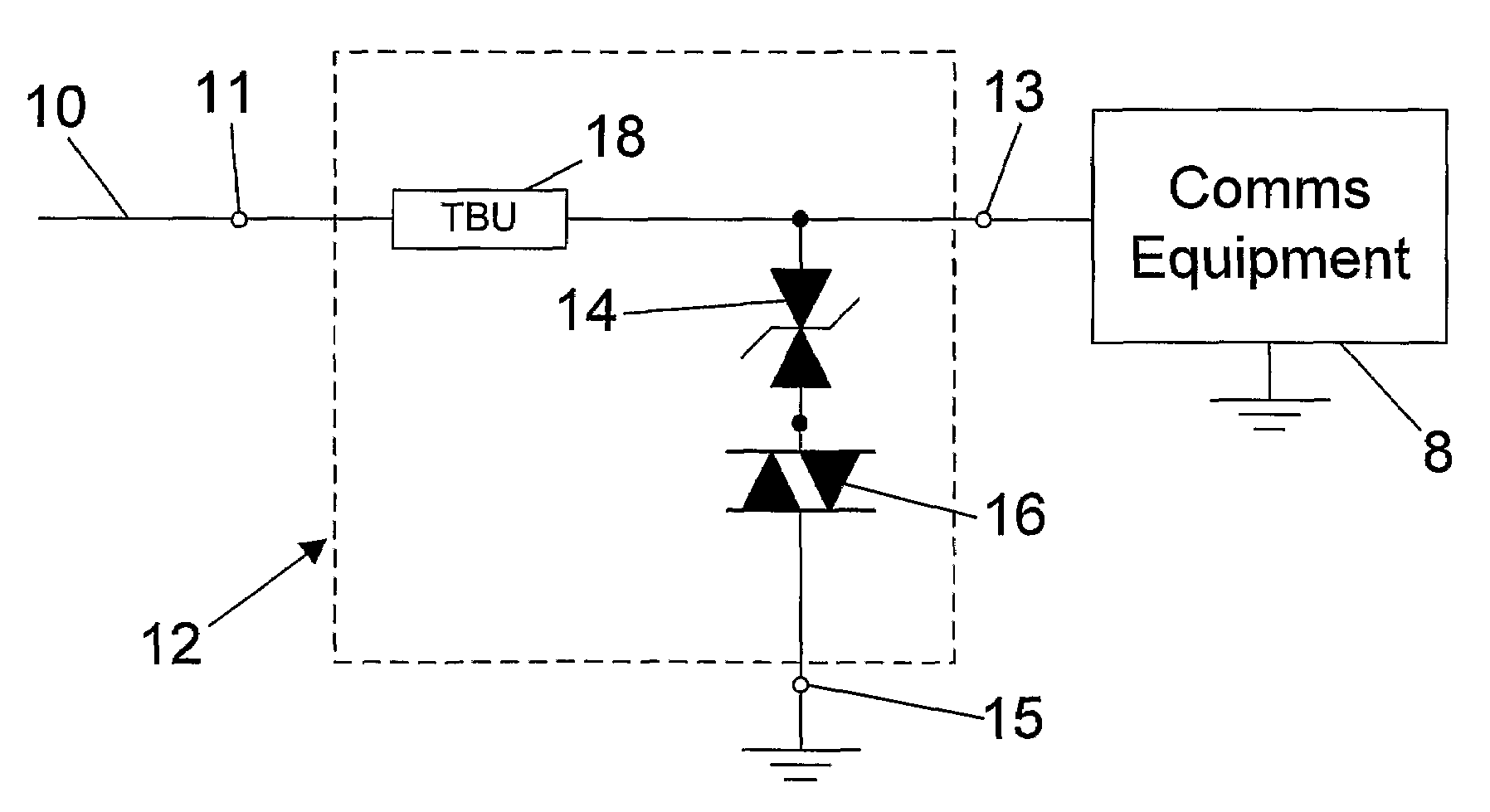
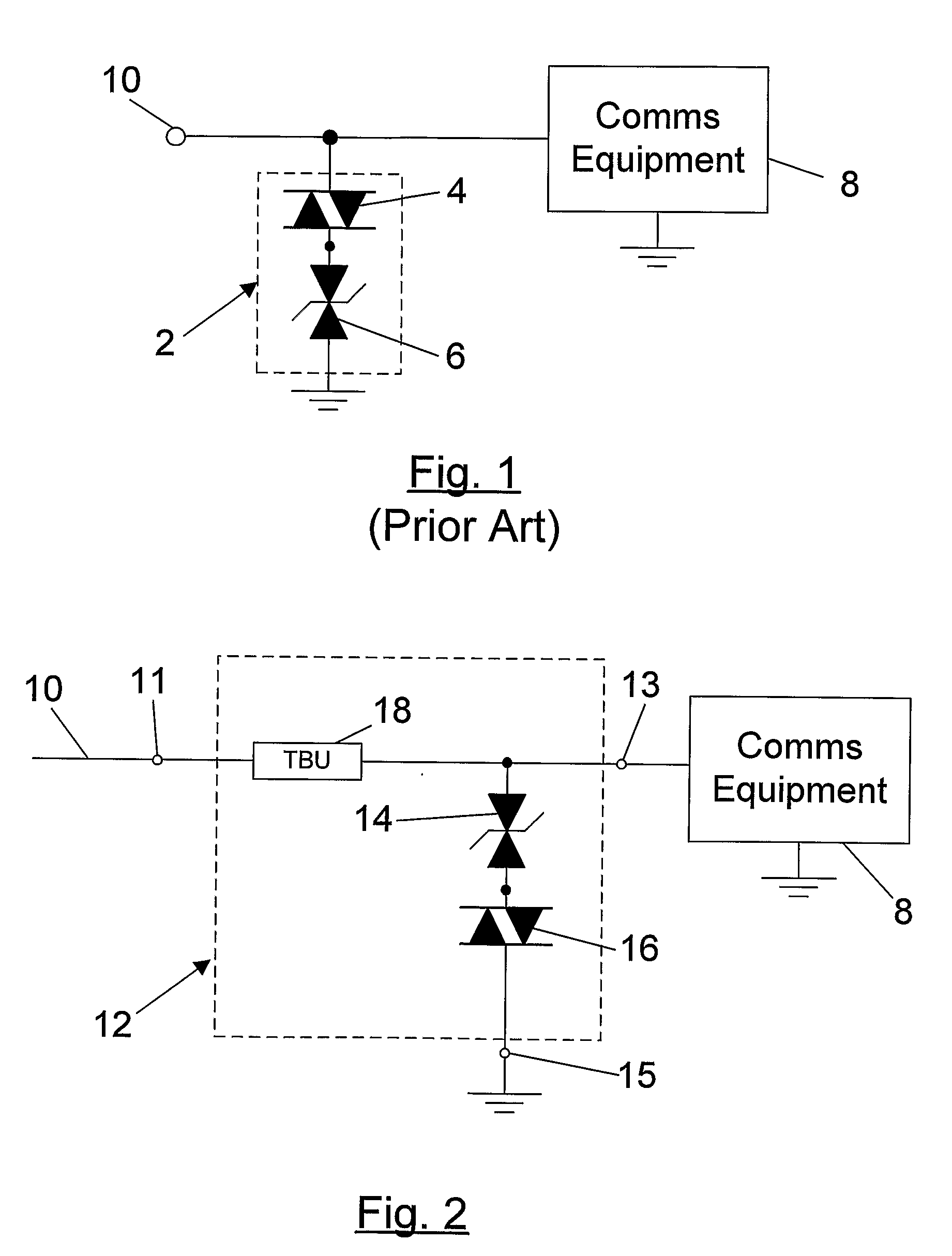
[0049]FIG. 2 depicts a surge protection circuit 12 according to a first embodiment of the present invention in use. Circuit 12 is connected, at input node 11, to a data or power supply line 10 and, at output node 13, to communication equipment 8. A surge sinking node, in the form of earth connection point 15, is connected to ground. Circuit 12 is designed to protect communication equipment 8 from voltage surges on line 10 as might be associated with a lightning strike or power supply malfunction. The circuit includes a series connected transient blocking unit (TBU) 18. TBU's are transistorised surge protection devices configured to assume an isolating state in response to an over-current passing through them. That is, they are transistor-based circuits configured to rapidly assume a very high impedance, i.e. to effectively open circuit or disconnec...


PUM


Abstract

An electrical surge protection device (12) confers protection to an output node (13) from electrical surges on a data or power line (10) incident on an input node (11). A transistorised surge protection device (18) is located in a current path between the input node (11) and the output node (13) and is configured to assume an isolating state in response to an over-current therethrough. A voltage-triggered protective circuit comprising a diac (16) in series with a bi-directional zener diode (14) is connected between the output side of the transistorised surge protection device (18) and a surge sinking node (15). The voltage-triggered circuit assumes a low-impedance state in response to an electrical surge at output terminal 13. Consequently a surge current is passed through zener diode (14) and surge diac (16) to the surge sinking node. In response to the surge current the transistorised surge protection device (18) assumes a high impedance configuration thereby isolating output node (13) from input node (11). Since neither the zener diode and diac combination, nor the transistorised surge protection device (18) are subject to sustained surge associated currents, embodiments of the invention can be compactly packaged.

Description

FIELD OF THE INVENTION[0001]The present invention relates to an electronic circuit for protecting equipment, such as data processing and communication equipment, from potentially damaging voltage surges.BACKGROUND TO THE INVENTION[0002]A reference to any prior art in this specification is not, and should not be taken as an acknowledgement or any form of suggestion that the prior art forms part of the common general knowledge.[0003]Various approaches have been taken in the past to protecting electronic equipment from potentially damaging voltage surges due to, for example, lightning strikes and power supply malfunctions.[0004]These approaches include the use of circuits incorporating metal oxide varistors (MOVs) and gas discharge tubes to short surges to ground before they are able to damage connected equipment. Such circuits are typically bulky and may have large associated capacitances which are undesirable.[0005]A circuit which does not make use of gas discharge tubes is described...

Claims


Application Information

Patent Timeline
Patent Type & Authority Applications(United States)
IPC IPC(8): H02H9/04H02H3/22
CPCH02H9/041H02H9/025
Inventor HARRIS, RICHARD A.
Owner BOURNS INC
Why Eureka
Try Eureka