Wide range proportional flow control valve

a flow control valve and wide-range technology, applied in valve arrangements, plug valves, mechanical equipment, etc., can solve the problems of additional system damage, leakage and damage of connected components, and inability to consistently deliver precise amounts of additives

Inactive Publication Date: 2000-08-29
TUTTLE JAMES D +1
View PDF2 Cites 41 Cited by
  • Summary
  • Abstract
  • Description
  • Claims
  • Application Information

AI Technical Summary

Benefits of technology

It is another feature of the present invention to provide a wide range flow control valve wherein any end range of relative motion of a flow port and a flow controlling aperture between the closed and full open positions thereof which may not have substantially exponential change per unit of relative motion be minimized.
It is a further feature of the present invention to provide a novel proportional flow control valve having a wide flow control range and also having the capability of smoothly controlling the opening, modulation and closing of the valve to avoid the occurrence of hydraulic shock during valve operation.
It is another feature of the present invention to provide a novel wide range proportional flow control valve that is designed to facilitate ease of manufacture and which will result in repeatable flow and control characteristics amongst like units.
The two endpoints, at the just-open end and just before the full-open condition is reached, are accompanied by significant variations in the value N. With suitable design, these regions are minimized, thus extending the range over which stable closed-loop control may be achieved.
The critical elements are a specially shaped aperture; and which provides exponential flow characteristics when mated with a port that blocks or coincides. Either, or both, could be moved during valve opening and closing, as long as there is motion of one relative to the other. Thus, the control valve mechanism may conveniently be provided in the form of a gate valve, slide valve, rotary ball valve, rotary plug valve, sleeve valve, etc. Any of these valve types, using the horn shaped flow control aperture, could give the desired flow control characteristics.

Problems solved by technology

While these methods are in wide use, their long-term reliability to consistently deliver precise amounts of additive is questionable.
The periodic pulsing with fast-rising and fast-falling pressure pulses that occurs in pulse-operated additive injection systems produces repetitive hydraulic shock, known as hydraulic "hammering" throughout the piping system, causing leaks and damage to connected components, such as joints and seals.
Cavitation, which may occur under certain conditions, can cause additional system damage.
The wide variations in flow characteristics of the various additives cause some of these devices to be operationally incapable of delivering the required precise amounts of additive at all times. These additive materials are relatively expensive.
This places severe limitations on the choice of compatible materials.
Contamination of the environment from leaks is very undesirable.
Excess flow due to leaking seals results in a significant economic loss in addition to potentially introducing amounts of additive that can be significantly in excess of the maximum allowable amounts, amounts that, if used on a consistent basis by motorists, might cause engine damage.
However, while the preset amount is "known" to the fuel delivery system, it frequently is not available to the additive delivery system.
While a wide flow range can be achieved using a bank of valves of differing flow capabilities, switching from one valve to another can be very difficult to effectively control as the required controlled flow varies from the range of one valve to that of another and back again, changing every few seconds as dynamic pressures of product and additive in a terminal vary.
While analysis suggested how an orifice could be designed to achieve the desired control characteristic, no currently available manufacturing technique was known to have been used to produce it.

Method used


Image

  • Wide range proportional flow control valve
  • Wide range proportional flow control valve
  • Wide range proportional flow control valve

Examples


Embodiment Construction

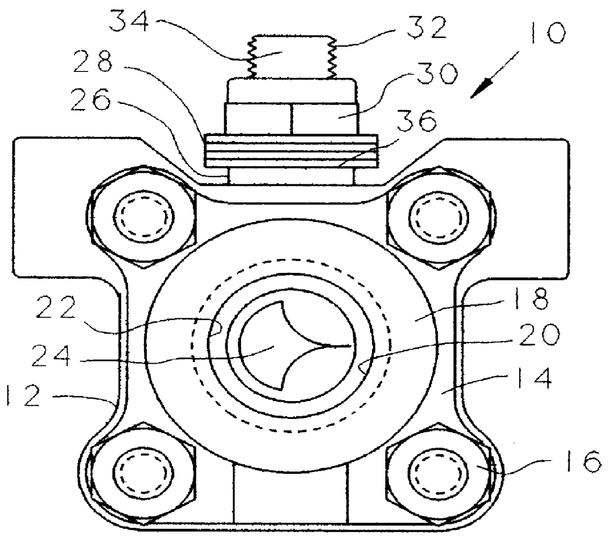
Referring now to the drawings and first to FIG. 1, a ball valve is shown generally at 10 having a valve body 12 which may be defined by body sections 14 that are secured in assembly by bolts 16. The valve body defines opposed connection means, one being shown at 18 and having inlet and outlet ports 20 which define a straight through flow passage for flow of fluid through the valve. The valve body 12 defines an internal valve chamber 22 within which is located a spherical valve element 24 defining a spherical external sealing surface and having a flow passage therethrough being defined by a transverse bore of cylindrical configuration and having circular openings at each end thereof where the transverse bore has intersection with the spherical sealing surface of the rotary spherical valve element. It should be borne in mind that the present invention need not be restricted to a valve of the ball valve type and that the invention is equally applicable to other valve types, such as rot...


PUM


Abstract

A continuous flow type proportional flow control valve having a very wide controllable flow range and having a valve seat port design permitting a continuous, stable closed loop control to be achieved. The flow port design cooperates with a simple cylindrical flow passage of a movable valve element and provides the valve with a very wide flow control range and the ability to smoothly control the opening, modulation, and closing of the valve to eliminate undesirable hydraulic shock which is an undesirable characteristic of pulse operated flow control systems. The flow controlling seat has a flow controlling port therein that cooperates with the flow port of the closure to define an effective valve opening that is proportionally variable over a wide range of closure movement. The seat port is provided with an extremely narrow elongate slot section less than +E,fra 1 / 50+EE th of the maximum width of the aperture. The seat opening also defines a large final, generally circular orifice section having a radius comparable to the radius of the bore in the ball. Further, the seat opening is defined by a transition between the elongate narrow slot and final circular orifice section in the form of two diverging curves offering an exponential flow characteristic of the form K=Nx.

Description

1. Field of the InventionThis invention relates generally to a method and apparatus for precisely controlled volumetric injection of selected fluid compositions through a flow control valve for any of a wide variety of purposes. More particularly, the present invention concerns the provision of a flow control valve having relatively movable flow control elements which are capable of cooperatively defining a flow control orifice opening having a valve closed condition blocking the flow of fluid through the valve, a full open condition for allowing maximum flow of fluid through the control valve and wherein the flow port and flow control aperture of the valve cooperate to provide for exponential percent change of the cross-sectional area of the flow control orifice per unit of relative valve element motion. In circumstances where the valve is provided for injection of various fuel additive compositions, the control valve mechanism provides for continuous flow type additive injection, ...

Claims


Application Information

Patent Timeline
Patent Type & Authority Patents(United States)
IPC IPC(8): F16K5/00F16K5/12
CPCF16K5/12
Inventor TUTTLE, JAMES D.SCHWARTZ, ROBERT J.
Owner TUTTLE JAMES D
Why Eureka
Try Eureka