Condenser microphone

a condenser microphone and microphone technology, applied in the field of condenser microphones, can solve the problems of increasing the number of steps, generating (or picking up) unnecessary impact sound of the microphone, and raising the cost of manufacturing, so as to reduce the impact sound

Inactive Publication Date: 2008-08-14
YAMAHA CORP
View PDF0 Cites 75 Cited by
  • Summary
  • Abstract
  • Description
  • Claims
  • Application Information

AI Technical Summary

Benefits of technology

[0007]It is an object of the present invention to provide a condenser microphone that can restrain an impact sound without masking.

Problems solved by technology

When a user mistakenly makes an impact on a microphone with something, the impact oscillates a diaphragm of the microphone so that the microphone generates (or picks up) an unnecessary impact sound.
The above-described conventional technique requires masking of a pick-up part of a microphone element with a resin sheet, and so it will increase number of steps in a manufacturing process and may raise a cost for manufacturing.

Method used


Image

  • Condenser microphone
  • Condenser microphone
  • Condenser microphone

Examples


first embodiment

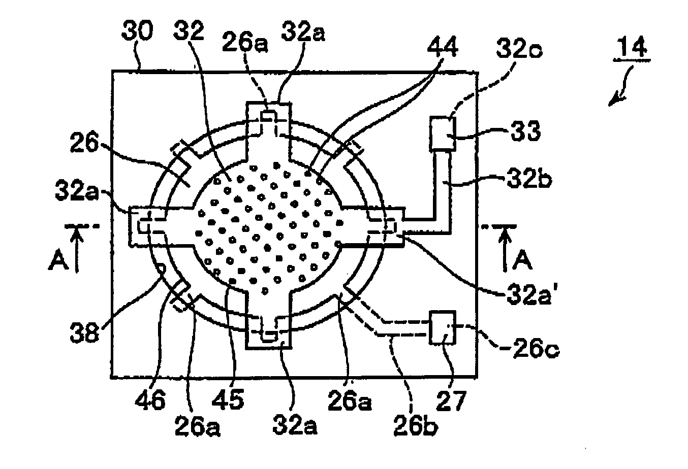
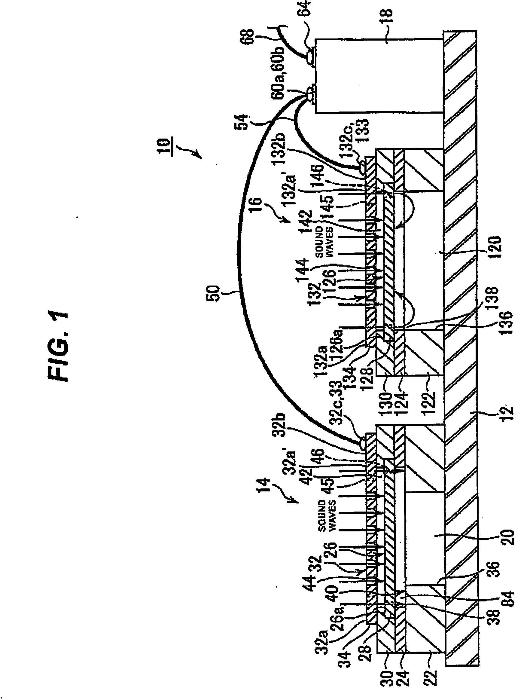
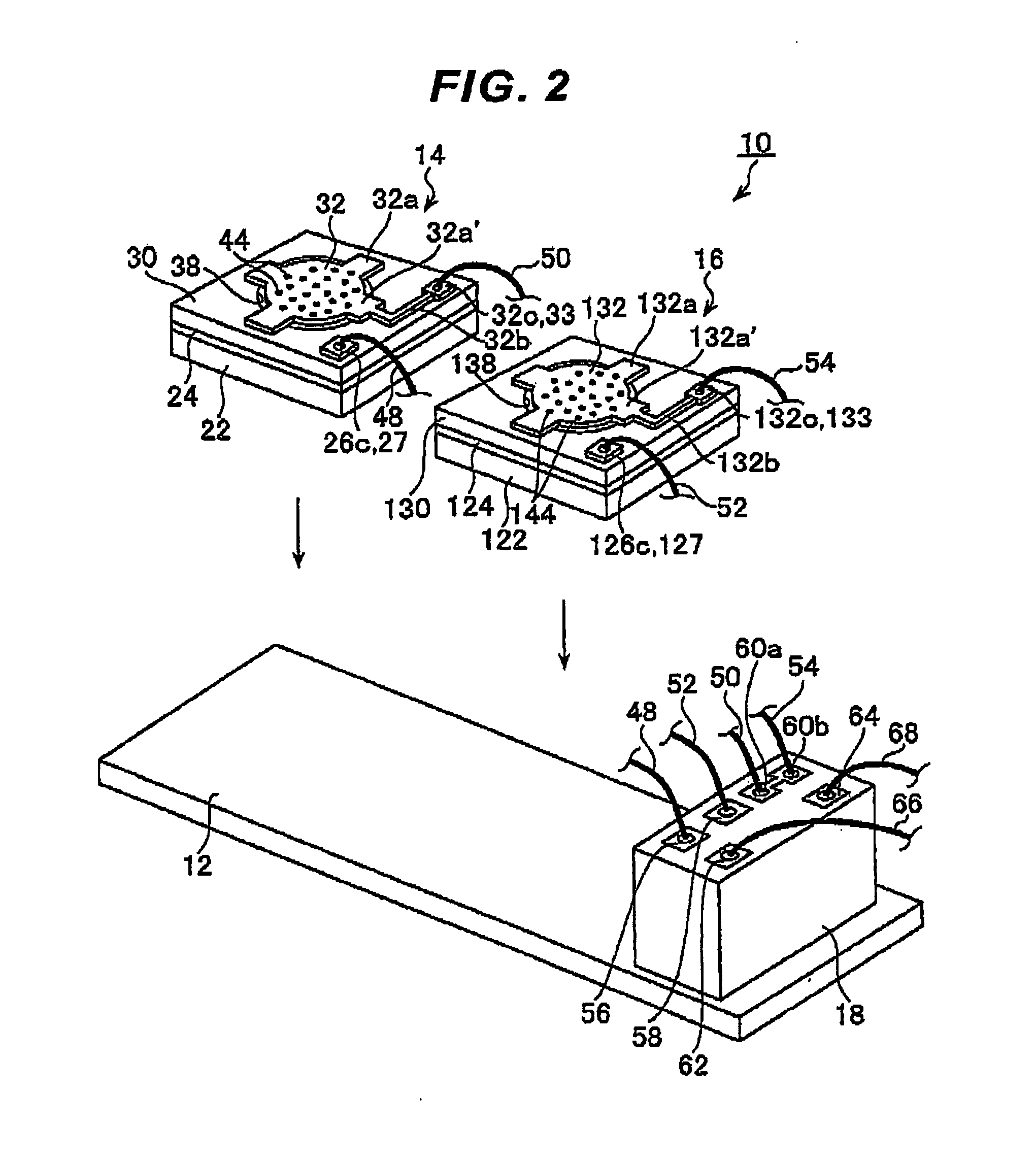
[0057]FIG. 1 is a cross sectional view of a condenser microphone 10 cut in a longitudinal direction according to the present invention. FIG. 2 is a decomposition perspective view of the condenser microphone 10.

[0058]As shown in FIG. 1, the condenser microphone 10 consists of a is device substrate 12 on which a condenser microphone element (a first condenser type element) 14, an acceleration sensor element (a second condenser type element) 16 and a LSI18 for impedance conversion are mounted by mutually being insulated with each another and fixed with adhesive. Both of the condenser type elements 14 and 16 are composed of condenser-typed elements and are positioned on the substrate 12 with the same surfaces facing a same direction. Opening ends of back cavities 20 and 120 of both elements 14 and 16 are sealed with the substrate 12. Both elements 14 and 16 are composed of the same measurement other than a diameter of opening parts 36 and 136 (explained later) composing main parts of th...

third embodiment

[0127]A terminal 329 for the diaphragm and a terminal 266 of a LSI 259 for impedance conversion on the condenser microphone element 214 are connected to each other by soldering a lead wire 270. A terminal 331 for the back plate and a terminal 268 of the LSI 259 for impedance conversion on the condenser microphone element 214 are connected to each other by soldering a lead wire 272. Lead wires 278 and 280 are respectively connected to terminals 274 and 276 of the LSI259 for impedance conversion. As described in the above, the circuit structure will be same as that in FIG. 15 showing the

[0128]Operations when sound waves by a sound from outside is input to the apparatus mounting the microphone assembly 264 and when an impact is given from outside such as hitting the apparatus to something will be explained. As shown in FIG. 17, when the sound waves are input from outside, the sound waves pass through the space 221 formed by the spacers 213, 215, 217 and 219 through the pierced hole 234...

fifth embodiment

[0130]FIG. 21 is a cross sectional view of a condenser microphone cut in a longitudinal direction according to the present invention. FIG. 22 is a decomposition perspective view of the microphone assembly in FIG. 21. As shown in FIG. 21, the condenser microphone 410 is configured of two pairs of condenser microphone elements 412 and 414. The condenser microphone elements 412 and 414 have a common back plate 416 and have diaphragms 422 and 424 respectively above and below the back plate 416 via spaces 418 and 420 with same height. The condenser microphone 410 is formed as a so-called silicon microphone by using the MEMS process. When the condenser microphone 410 is relatively large, individual parts can be configured by assembling.

[0131]Detailed configuration of the condenser microphone 410 will be explained. The condenser microphone 410 is formed by sequentially forming an insulating layer 428 made of a silica-film, etc., the diaphragm 424, an insulating layer 430, the back plate 41...


PUM


Abstract

A condenser microphone 14 and an accelerometer 16 are placed on a device substrate 12 with arranging same sides in a same direction. Both condenser microphone 14 and accelerometer 16 are formed of condenser microphones. Sizes of the condenser microphone 14 and accelerometer 16 are same other than diameters of back cavities 20 and 120. A step 40 that decreases an inner diameter of the back cavity 20 is formed inside the back cavity 20 to function as an audio resistance, whereas the back cavity 120 of the accelerometer 16 has no step (audio resistance). A microphone output is obtained by subtracting a terminal voltage of the condenser microphone 14 by a terminal voltage of the accelerometer 16.

Description

CROSS REFERENCE TO RELATED APPLICATION[0001]This application is based on Japanese Patent Application 2007-031377, filed on Feb. 9, 2007, Japanese Patent Application 2007-031378, filed on Feb. 9, 2007, and Japanese Patent Application 2007-059543, filed on Mar. 9, 2007, the entire contents of which are incorporated herein by reference.BACKGROUND OF THE INVENTION[0002]A) Field of the Invention[0003]This invention relates to a condenser microphone including an electret condenser microphone and more specifically to a condenser microphone that can restrain generation of noise caused by an impact of something on the condenser microphone.[0004]B) Description of the Related Art[0005]When a user mistakenly makes an impact on a microphone with something, the impact oscillates a diaphragm of the microphone so that the microphone generates (or picks up) an unnecessary impact sound. Japanese Laid-open Patent No. 2001-36607 discloses a technique for restraining generation of that kind of an impact...

Claims


Application Information

Patent Timeline
Patent Type & Authority Applications(United States)
IPC IPC(8): H04R9/08
CPCH04R19/005H04R19/04H01L2224/48091H01L2224/48137H01L2924/1461H01L2924/3011H01L2924/00014H01L2924/00
Inventor SATO, AKIYOSHI
Owner YAMAHA CORP
Why Eureka
Try Eureka