
Electronic Pipetting Device for Aspirating and Dispensing of Set Liquid Volumes

a technology of liquid volume aspiration and pipetting device, which is applied in the direction of withdrawing sample device, material testing goods, chemical methods analysis, etc., to achieve the effect of convenient control

Inactive Publication Date: 2008-08-14
P Z HTL SPOLKA AKCYJNA
View PDF6 Cites 8 Cited by
  • Summary
  • Abstract
  • Description
  • Claims
  • Application Information

AI Technical Summary

Benefits of technology

[0009]The next aim of the invention is to provide a pipetting device, comprising a structure, assuring a mobility of the control panel in two degrees of freedom with regards to the handle and such a mutual configuration of pipetting, programming and ejector buttons, as well as of the data display location on the mobile control panel and the handle as to provide the user with the most comfortable for him positioning of the pipetting device components and to enable proper operation of the said device.
[0010]The next aim of the invention is to provide a pipetting device, comprising a structure, which assures a stable setting of a previously determined and convenient position of the control panel with regards to the handle during the operation of the said device.
[0013]What is advantageous in the said device, following the invention, is the mechanism for stable setting of the angular position and / or the longitudinal position of the control panel with respect to the handle.
[0014]The advantage of the solution, following the invention, is that it provides, in parallel, firm handling of the ergonomically designed handle and proper operation of the said device by the user.
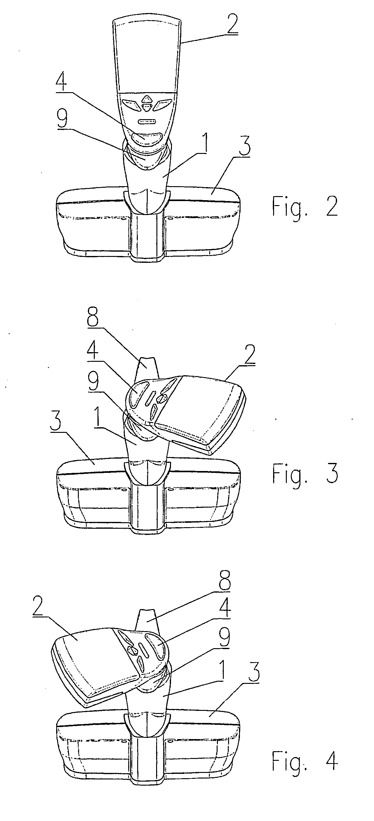
[0015]Moreover, an operator, can, in general, arbitrarily move and rotate as well as determine the position of the control panel with respect to the handle to conveniently control the said device via an easy access to the pipetting and programming buttons on the control panel and to the ejector button on the handle with a simultaneous ability to observe the data display on the mobile control panel.

Problems solved by technology

In the known solutions, there is a problem with the adjustment of setting and control elements of the pipetting device to the size of the operator's palm and to his preferences in operating the said device.

Method used


Image

  • Electronic Pipetting Device for Aspirating and Dispensing of Set Liquid Volumes
  • Electronic Pipetting Device for Aspirating and Dispensing of Set Liquid Volumes
  • Electronic Pipetting Device for Aspirating and Dispensing of Set Liquid Volumes

Examples


Embodiment Construction

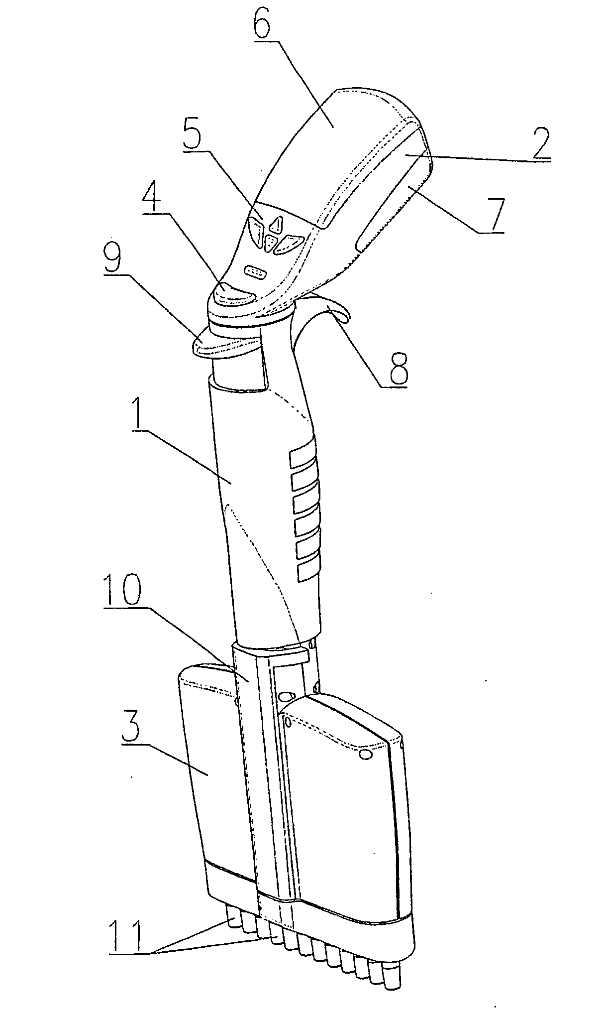
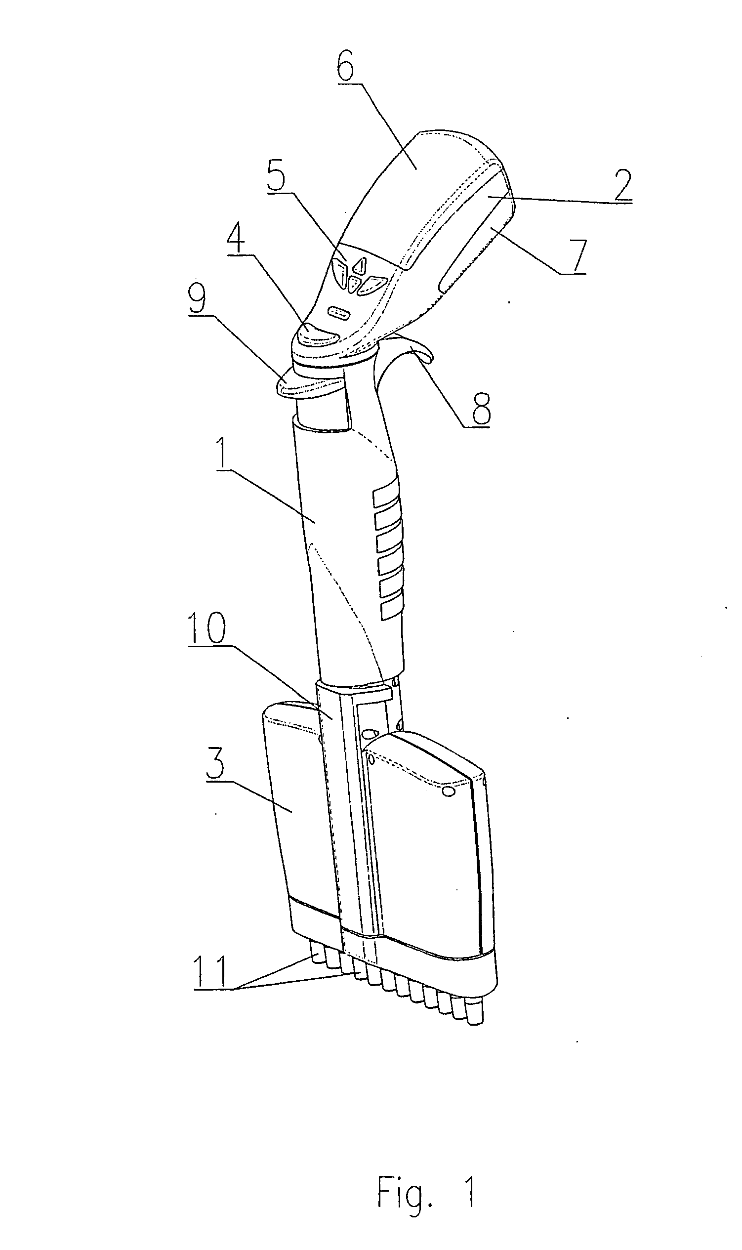
[0024]The electronic pipetting device, as presented in the general view in FIG. 1, comprises a generally cylindrical handle 1, to the upper part of which, a control panel 2 is attached, while to its lower part, a detachable stem assembly is attached, where the term ‘detachable stem’ is to be understood as single- or multichannel stem 3.

[0025]The control panel 2 is connected with the handle 1 in such a way that it can rotate with respect to the longitudinal axis of the handle 1 and in a plane, perpendicular to it, by angle, set up by the operator of the pipetting device. The control panel 2 comprises a programmed electronic system controlling the operation of the whole pipetting device. The control panel 2 has a pipetting button 4, which rotates together with it around the longitudinal axis of the handle 1 and, in its upper part, a series of programming buttons to enter the device operation parameters into the electronic system, and a display 6 of data, entered to the electronic memo...


PUM


Abstract

An electronic pipetting device for aspirating and dispensing of set liquid volume comprises a handle (1), to the lower part of which a stem assembly (3) is attached, and a control panel (2), whereas the control panel (2) is connected with the handle (1) in such a way that it can rotate with respect to the longitudinal axis of the handle (1) and / or move it upwards and parallel to the longitudinal axis of the handle (1).

Description

TECHNICAL FIELD [0001]The invention relates to an electronic pipetting device for aspirating and dispensing of set liquid volumes.BACKGROUND ART[0002]The pipetting device, known from the U.S Pat. No. 4,054,062, designed for aspirating and dispensing of set liquid volume, comprising an upper part, cylindrically shaped and standing for its handle, and a lower cylindrical part, attached to the said handle. The free end of the lower part is conically shaped for engaging the interior of disposable pipette tips. Moreover, the handle has got a protruding hold for the operator's finger and, in the upper free end, there is a pipetting button and an ejector button which is attached to the cylinder of disposable tips, surrounding the lower part of the said device.[0003]In turn, the portable, electronically programmable automatic pipette, known from the U.S Pat. No. 4,905,526, comprises a linear module of the driving mechanism with a module driving motor, contained in a hand held housing, a con...

Claims


Application Information

Patent Timeline
Patent Type & Authority Applications(United States)
IPC IPC(8): B01L3/02
CPCB01L3/0227B01L2200/087B01L3/0237B01L3/02G01N1/14
Inventor CZERNECKI, ANDRZEJWYSZOGRODZKI, WOJCIECHURBAN, PIOTRJANKOWSKI, ANDRZEJ
Owner P Z HTL SPOLKA AKCYJNA
Learn More