Ribbon bonding tool and process

a ribbon and tool technology, applied in the direction of manufacturing tools, soldering devices, auxillary welding devices, etc., can solve the problems of reducing the bonding strength of the surface, affecting the bonding performance of the surface, so as to achieve the effect of high strength bonded areas and lighter strength

Active Publication Date: 2008-08-14
ORTHODYNE ELECTRONICS
View PDF12 Cites 3 Cited by
  • Summary
  • Abstract
  • Description
  • Claims
  • Application Information

AI Technical Summary

Benefits of technology

[0016]According to one aspect of the present invention, a method for ultrasonic bonding includes first applying bond force and ultrasonic vibration to the ribbon (or wire) only to specific areas of the ribbon to quickly deform and create bonded spots at those depressed areas. The bonding then continues by pushing or driving the tool further into the ribbon such that all areas of the ribbon, including areas between the depressions deform and create a bond over the entirety of the ribbon bond area. The result is a bond that has high strength bonded areas in the depressed areas and possibly lighter strength bonded areas between the depressed areas. Further, the stronger bonded areas are evenly distributed throughout the entire bond.
[0018]In one embodiment, the tool foot structure is designed such that the teeth can quickly (after applying ultrasonic vibrations) penetrate the ribbon material to deform the ribbon under the teeth to a thickness of approximately 100 μm or less. This creates bonded spots of high strength under the teeth, instead of a weaker bonded area spread over the complete tool foot, which is the case for conventional bonding. After the teeth have penetrated a distance greater than the groove depth of the tool, i.e., the ribbon now contacts the complete surface area of the tool, the ultrasonic power and force are spread over the complete area of the tool foot. This causes the bonded area to grow into the spaces between the initially bonded spots. But because of the lower power and force density, resulting in a lower material shear flow, the bond strength in these areas could be weaker. However, this does not cause a problem, especially if the ribbon in the areas between the teeth is in direct contact with the substrate. Even if the local bond strength in these areas is rather weak, the joint will not delaminate in these areas, as long as they are surrounded by intact strongly bonded depression areas.
[0019]Thus, advantages of the present invention include creation of bonds that are stronger and therefore more reliable under thermal cycling, bonds of equal length and width but different (ribbon) thickness with virtually the same parameters regarding ultrasonic power and bond force, i.e., with parameters that increase much less than proportional to the ribbon's thickness, and larger bonds, especially longer bonds than capable with traditional tools (under force / power constraints of a specific bonder system). In other words, the invention allows achieving (1) bonds with better reliability (under thermal and power cycling), (2) a significant reduction of the dependence of the bond parameters on ribbon thickness, and therefore a scaling to thicker ribbons, (3) a wider process window, (4) larger contact areas from larger tool foot sizes and (5) larger contact areas from multiple adjacent bonds (“continuous bond”).
[0020]According to another embodiment, an ultrasonic bond is formed on a ribbon, wherein the bond does not extend the complete width of the ribbon. In one embodiment, the shape of the bond is circular, and in another embodiment, the shape of the bond is square. With wider ribbons, such as 3 mm, an effective bond can be made in the interior portion, such as the inner 1.5 or 2 mm. Under limited bond force and power requirements, it may be advantageous to not bond the complete width of the ribbon. To a first order, the crack growth rate within a bond along and perpendicular to the ribbon is the same. Therefore, a square or round bond instead of a rectangular one would be a more optimized shape in applications where the length of the bond is not dictated by space restrictions. Not bonding the complete width of a ribbon does not cause a disadvantage or problem from either a performance or a reliability aspect. Consequently it is also possible to partially bond even wider ribbons, as long as the contact area is large enough to allow the large current flow possible through the larger ribbon cross section. This method also enables using and bonding such wide ribbons which would cause planarity related issues when bonded across their complete width.

Problems solved by technology

However, for the round wire's geometry, the surface extension is much more extensive with limited bond parameters (e.g., force and power) than for bonding rectangular ribbon.
This failure mode transition may occur because under thermal or power cycling the bond interface degrades quicker than the heel.
But because of the lower power and force density, resulting in a lower material shear flow, the bond strength in these areas could be weaker.
This method also enables using and bonding such wide ribbons which would cause planarity related issues when bonded across their complete width.

Method used


Image

  • Ribbon bonding tool and process
  • Ribbon bonding tool and process
  • Ribbon bonding tool and process

Examples


Embodiment Construction

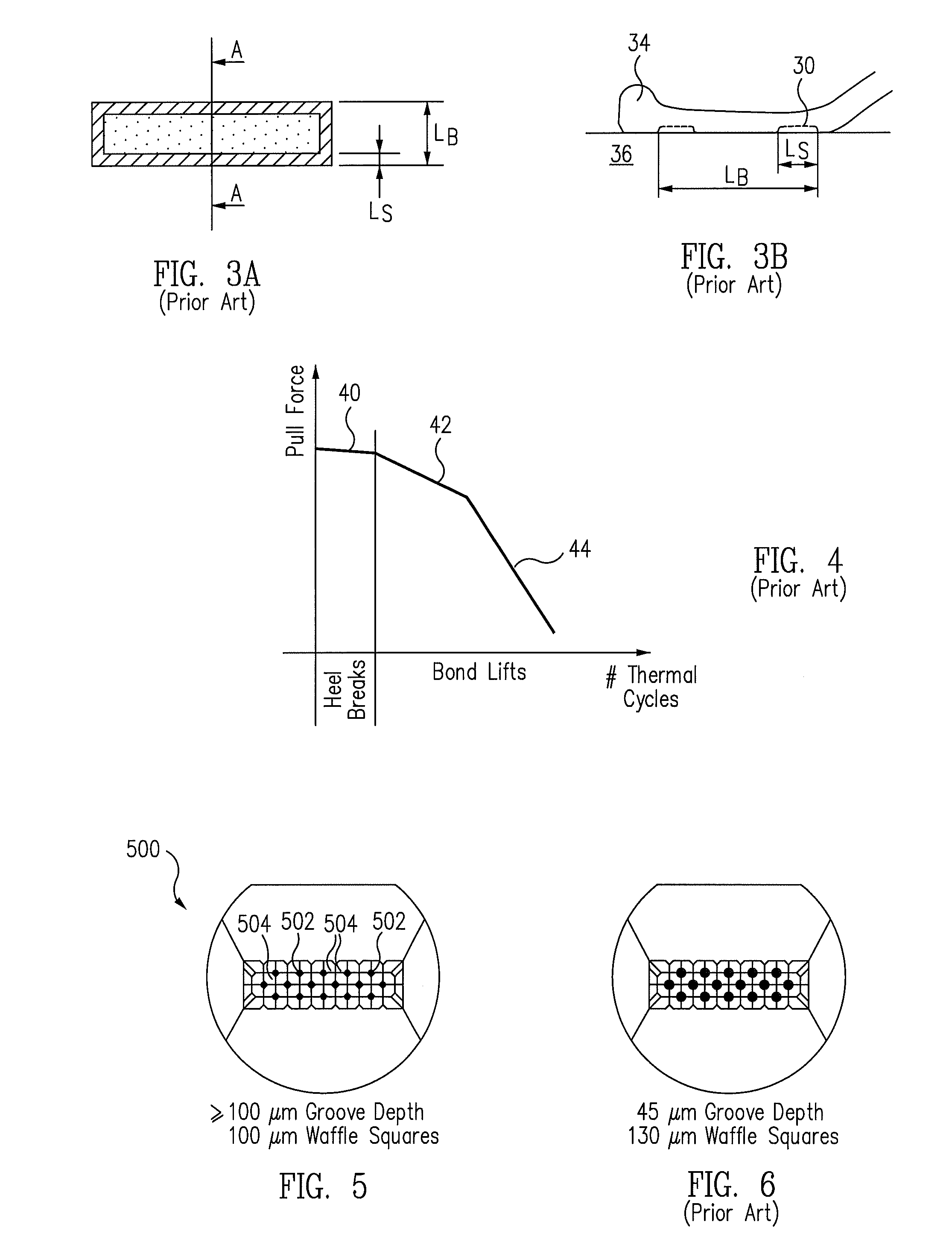
[0038]According to one aspect of the present invention, a bonding tool for ultrasonic bonding comprises a bond foot having deeper grooves and narrower or thinner teeth or protrusions, as compared with conventional waffle tools. FIG. 5 is a bottom view of a bonding tool 500 according to one embodiment. Bonding tool 500 includes a plurality of teeth or protrusions 502 and a plurality of grooves 504 between teeth 502. In one embodiment, the depth of grooves 504 (or the length of teeth 502) is approximately greater than 100 μm, and the width of teeth 502 is approximately 100 μm. This allows more effective ribbon bonding by bringing the teeth closer to the bond interface before the bond tool contacts the remaining portions of the ribbon, as will be discussed in more detail below. Conventional waffle bonding tools, such as that shown in FIG. 6, have shallower grooves (or shorter teeth) (e.g., 45 μm) and larger teeth (e.g., 130 μm). Thus, an exemplary bonding tool of the present invention ...


PUM

PropertyMeasurementUnit
thicknessaaaaaaaaaa
widthaaaaaaaaaa
distanceaaaaaaaaaa

Abstract

An ultrasonic bond is formed using a bond tool foot having a waffle shape of thin protrusions and gaps between the protrusions. The tool is brought in contact with the ribbon to a depth to create depressions in a ribbon approximately 150 μm or less from the underlying bonding surface. The tool is then brought down further into the ribbon to contact the portions of the ribbon between the depressions, such as an additional 25 to 50 μm. The result is lightly bonded regions underneath the groove portions and highly bonded regions underneath the protrusions and around the perimeter of the bond. In another embodiment, an ultrasonic bond is formed along a partial width of a ribbon.

Description

[0001]This application is a divisional of U.S. patent application Ser. No. 11 / 044,695, filed Jan. 27, 2005, which is herein incorporated by references for all purposes.BACKGROUND[0002]1. Field of the Invention[0003]The present invention relates to bonding of semiconductor devices, and in particular, to tools and processes for ultrasonic ribbon bonding.[0004]2. Related Art[0005]In the manufacture of semiconductor devices, active elements in a semiconductor device, such as drain and / or source regions in a semiconductor die, are electrically connected to other devices or electronic components, such as on a printed circuit board. Typically, the connection is made by bonding, e.g., ultrasonically bonding, a conductive wire between the two portions. The wire can be made from gold, aluminum, or copper, with typical diameters from 12 μm to 500 μm. Examples of electrical connections which can be made using wire bonding techniques include connections between the contact surfaces of discrete o...

Claims


Application Information

Patent Timeline
Patent Type & Authority Applications(United States)
IPC IPC(8): B32B3/26
CPCB23K20/004B23K20/106H01L24/45H01L24/48H01L24/78H01L24/85H01L2224/45014H01L2224/45015H01L2224/45124H01L2224/45144H01L2224/45147H01L2224/45565H01L2224/4807H01L2224/48458H01L2224/48472H01L2224/48599H01L2224/48699H01L2224/78313H01L2224/85205H01L2924/01005H01L2924/01006H01L2924/01013H01L2924/01014H01L2924/01029H01L2924/01032H01L2924/01079H01L2924/01082H01L2924/10253H01L2924/13091H01L2924/20751H01L2924/20752H01L2924/20753H01L2924/20754H01L2924/20755H01L2924/20756H01L2924/20757H01L2924/20758H01L2924/20759H01L2924/2076H01L2924/01033H01L2924/01068Y10T428/24612Y10T428/24488Y10T428/2495Y10T428/24942H01L2224/78315H01L2924/00011H01L2924/00014H01L2924/00
Inventor DELSMAN, MARK ARNOLDLUECHINGER, CHRISTOPH BENNO
Owner ORTHODYNE ELECTRONICS
Why Eureka
Try Eureka