Combined open and closed loop power control in a communications satellite

a technology of open and closed loop power control and communications satellite, which is applied in power management, multiplex communication, frequency-division multiplex, etc., can solve the problems of poor propagation and even signal loss, power addition is neither possible nor desirable, and prior approaches do not take into account both short-term and long-term degradation factors along propagation paths. , to achieve the effect of rapid closed loop power control

Active Publication Date: 2008-08-14
VIASAT INC
View PDF11 Cites 13 Cited by
  • Summary
  • Abstract
  • Description
  • Claims
  • Application Information

AI Technical Summary

Benefits of technology

[0007]According to the invention, in a telecommunication network where a wireless path is provided between a transmitter and a receiver via a satellite relay forming a multi-hop relayed signal path, a method and system are provided for furnishing adequate signal at a user terminal, which may be in motion, along the propagation path, the method including an open loop component that uses measurements of fading in a received signal at a first terminal to adjust transmit power from the first terminal and further includes a closed loop component that uses measurements of fading in the received signal at a second terminal along with an acknowledgement message and power correction. A speed estimation is employed in the open loop correction control signal path to modulate relatively long-term effects associated with terminal ground speed, along with more rapid closed loop power control.

Problems solved by technology

Various impediments in a transmission path can cause poor propagation and even loss of signal, including weather, interference, signal reflection, signal blockage, multi-path, and the like.
In an environment where a celestial relay station is used, in particular via an orbiting satellite which is subject to severe power budget restrictions, simply adding power is neither possible nor desirable.
Notably, prior approaches did not take into account both short-term and long-term degradation factors along propagation paths.
The problem of assuring adequate power to the user terminal at the point of reception is further complicated if the terrestrial terminal is in motion, such as on a motor vehicle or an aircraft.

Method used


Image

  • Combined open and closed loop power control in a communications satellite
  • Combined open and closed loop power control in a communications satellite
  • Combined open and closed loop power control in a communications satellite

Examples


Embodiment Construction

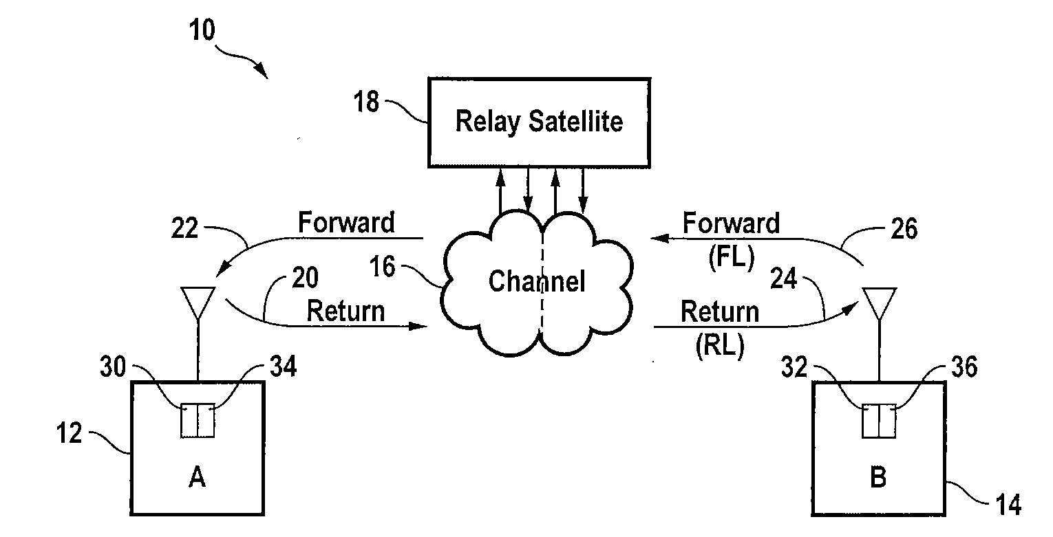
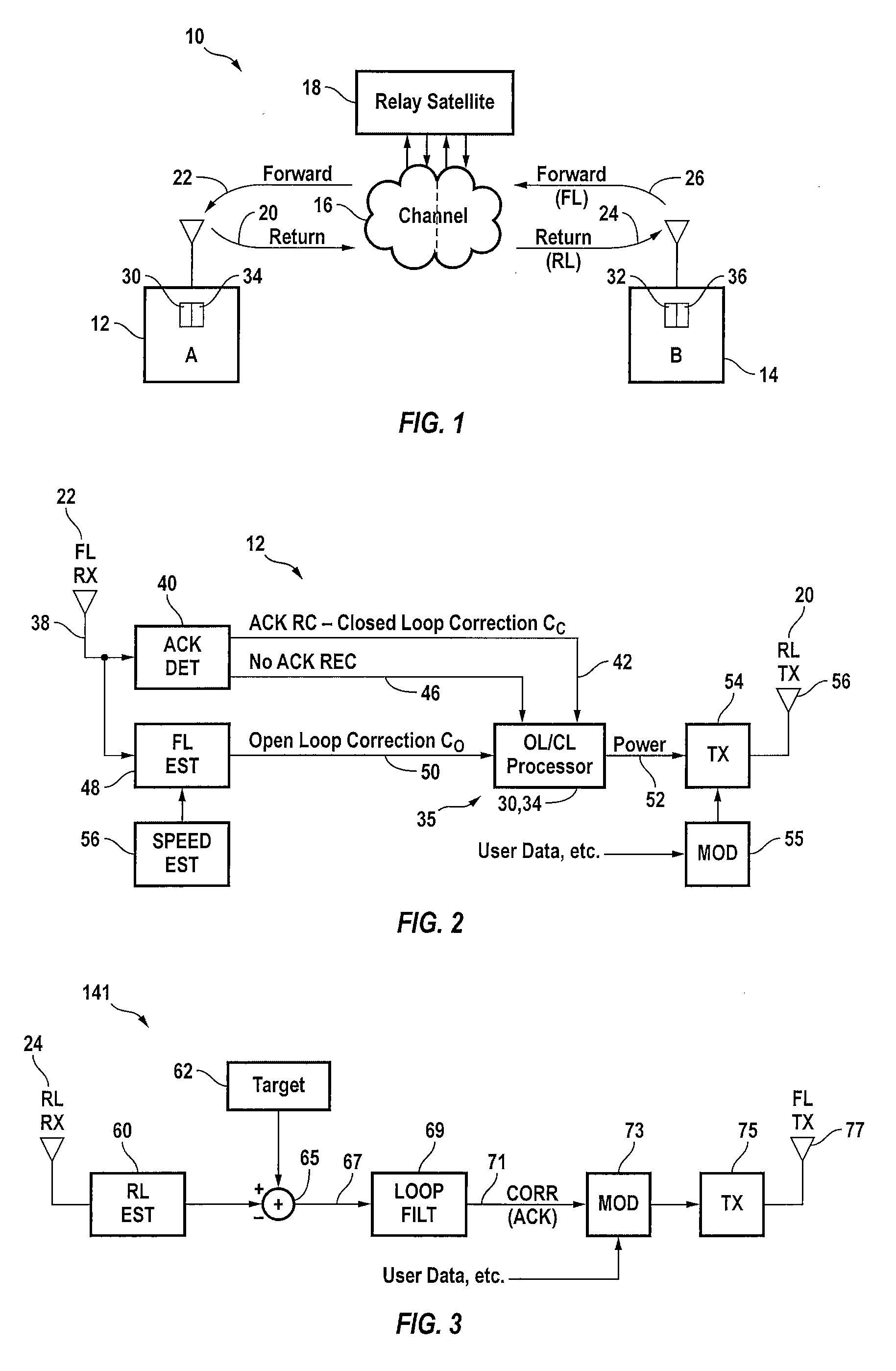
[0025]FIG. 1 illustrates a system 10 in an environment in which the invention is implemented. Two terminals A 12 and B 14, at least one of which may be in motion from time to time, are coupled in communication via a communication cloud 16 with a relay for example through a communication satellite 18. The terminals A 12 and B 14 communicate bi-directionally over a bi-directional communication channel of segments 20, 22, 24, 26 as hereinafter explained and that may be subject to degradation, such as short term and long term fading and other propagation effects, including transient interference. The transmission direction from Terminal B to Terminal A is called the forward link (FL) direction and is composed of segments 26 and 22, and the transmission direction from Terminal A 12 to Terminal B 14 is called the return link (RL) direction and is composed of segments 20 and 24. More specifically, the forward link (FL) direction comprises an uplink segment (FUL) 26 and a downlink segment (...


PUM


Abstract

In a telecommunication network where a wireless path is provided between a transmitter and a receiver via a satellite relay forming a multi-hop relayed signal path, a method and system are provided for furnishing adequate signal at a user terminal, which may be in motion, along the propagation path, the method including an open loop component that uses measurements of fading in a received signal at a first terminal to adjust transmit power from the first terminal and further includes a closed loop component that uses measurements of fading in the received signal at a second terminal along with an acknowledgement message and power correction.

Description

CROSS-REFERENCES TO RELATED APPLICATIONS[0001]The present application claims benefit under 35 USC §119(e) of U.S. provisional Application No. 60 / 889,017, filed on Feb. 9, 2007, entitled “Combined Open And Closed Loop Power Control,” the content of which is incorporated herein by reference in its entirety.STATEMENT AS TO RIGHTS TO INVENTIONS MADE UNDER FEDERALLY SPONSORED RESEARCH OR DEVELOPMENT[0002]Not ApplicableREFERENCE TO A “SEQUENCE LISTING,” A TABLE, OR A COMPUTER PROGRAM LISTING APPENDIX SUBMITTED ON A COMPACT DISK[0003]Not ApplicableBACKGROUND OF THE INVENTION[0004]This invention relates to wireless communication via a satellite relay and more particularly to regulation of signal power in a wireless network using a satellite relay.[0005]In a communication environment, power control is a the process by which power level or EIRP of transmissions is adjusted in the presence of varying propagation conditions in order that signals arrive at an intended receiver at a signal level ...

Claims


Application Information

Patent Timeline
Patent Type & Authority Applications(United States)
IPC IPC(8): H04B7/185
CPCH04B7/18543H04W52/08H04B7/18506H04W52/282H04W52/10
Inventor MARTIN, TIMOTHY J.O'NEILL, JOHN HAIHAMEL, ANTHONY GUYMILLER, MARK J.
Owner VIASAT INC
Why Eureka
Try Eureka