Light-guided transluminal catheter

Inactive Publication Date: 2008-08-14
CHILDRENS MEDICAL CENT CORP
View PDF101 Cites 88 Cited by
  • Summary
  • Abstract
  • Description
  • Claims
  • Application Information

AI Technical Summary

Benefits of technology

[0047]In a further embodiment further including a heat sink in said tubular member and ext

Problems solved by technology

However, this technique is only possible in cases where the catheter is of a

Method used


Image

  • Light-guided transluminal catheter
  • Light-guided transluminal catheter
  • Light-guided transluminal catheter

Examples


Example

[0069]While the invention is amenable to various modifications and alternative forms, specifics thereof have been shown by way of example in the drawings and will be described in detail. It should be understood, however, that the intention is not to limit the invention to the particular embodiments described. On the contrary, the intention is to cover all modifications, equivalents, and alternatives falling within the spirit and scope of the invention as defined by the appended claims.

DETAILED DESCRIPTION

[0070]In general, the present invention is directed to medical devices and more particularly to a light-guided catheter for direct visualization of placement through the skin. The catheter may be placed intracorporeal (inside the body) by any of the catheterization techniques known to those skilled in the art, and the invention includes, but is not limited to intravenous, intraarterial, or intraluminal placement of the catheter.

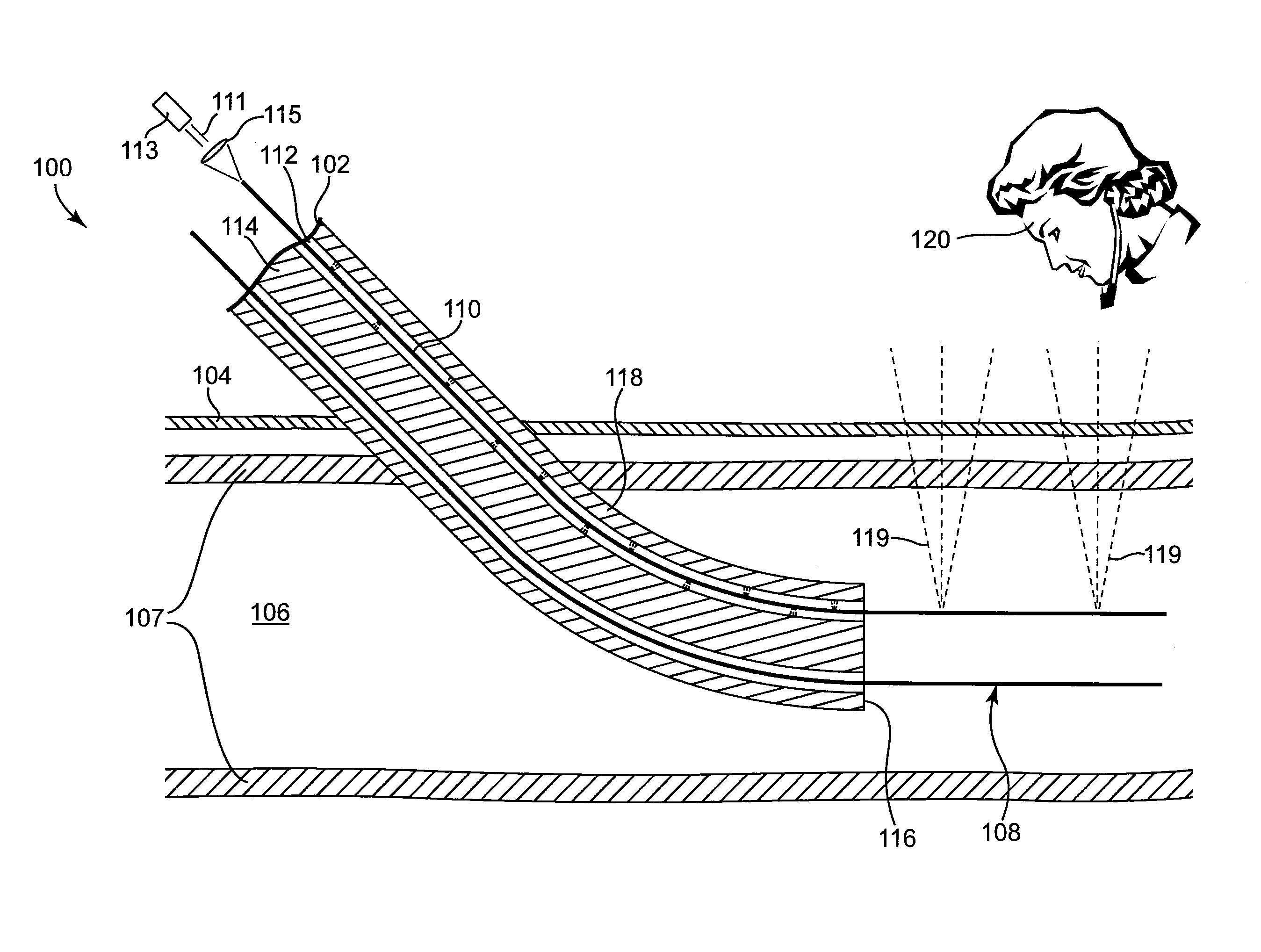
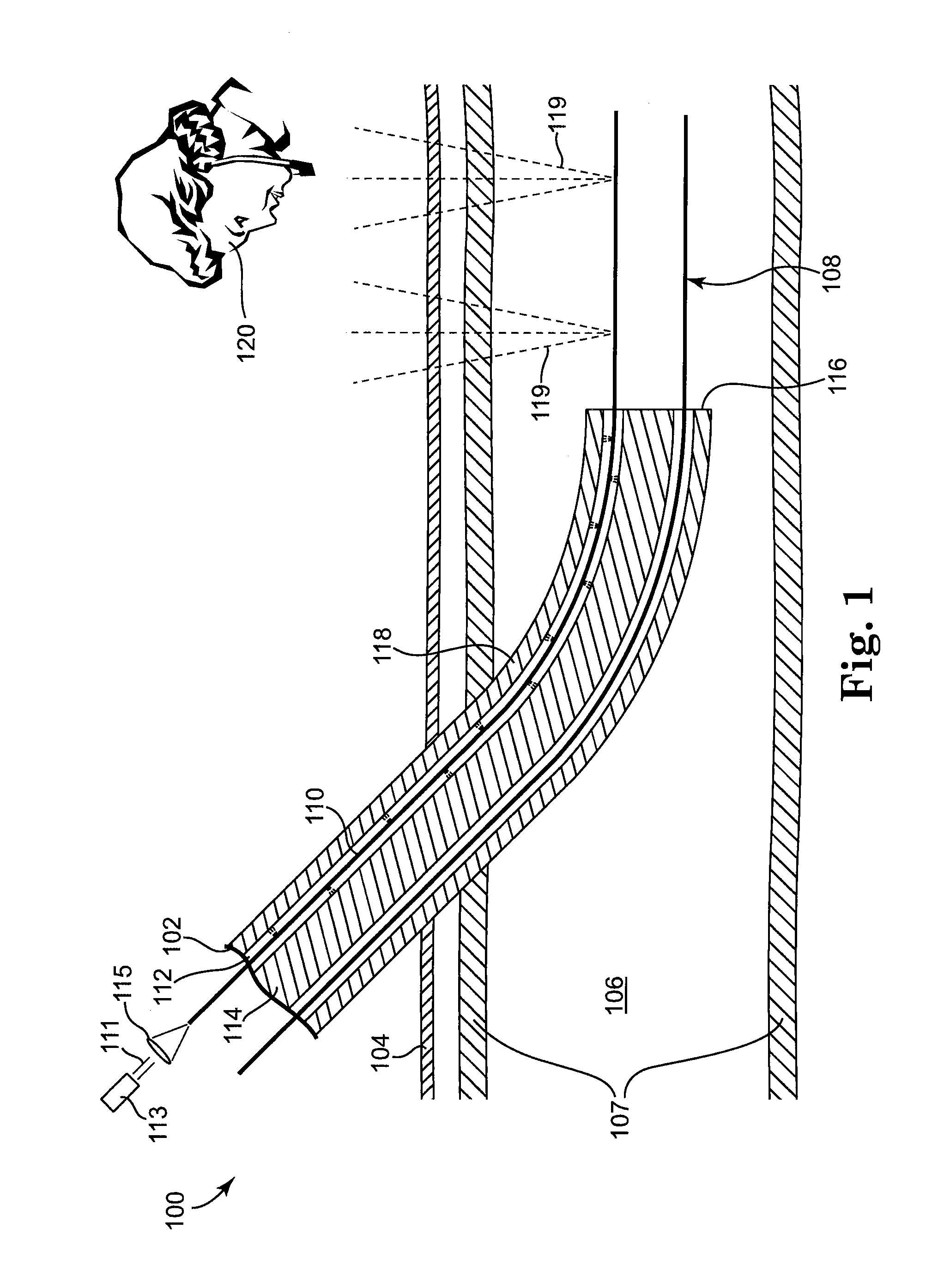
[0071]One embodiment of a light-guided transluminal cat...


PUM


Abstract

Generally, the present invention is directed to a light-guided catheter for direct visualization of placement through the skin. An embodiment of the invention includes a method for transcutaneous viewing and guiding of intracorporeal catheters into a body that comprises inserting a catheter into the body having at least one lumen and internally illuminating the catheter with light capable of propagating through the blood and tissue to an external viewer outside of the body. The illumination may be point source, continuous, single or multi wavelength. A method of treatment of blood conditions is also disclosed using direct placement of a photo treatment source in the blood stream.

Description

CROSS-REFERENCE TO RELATED APPLICATIONS[0001]The present application is a continuation-in-part of prior application Ser. No. 11 / 509,203 filed Aug. 24, 2006, which claims the benefit of 60 / 716,454 filed Sep. 13, 2005 and 61 / 024,666 filed Jan. 30, 2008.FIELD OF INVENTION[0002]The present invention is directed generally to medical devices and more particularly to a light-guided catheter with inside-out transcutaneous illumination and visualization of placement through the skin including a method to locate non-visible blood vessels for catheterization.BACKGROUND[0003]Generally, to insert a catheter into a blood vessel, the vessel is initially identified via aspiration by a syringe with an attached hollow needle by a technique commonly referred to as the Seldinger technique. When blood is drawn into the syringe, this indicates that the vessel has been found. The syringe is then disengaged from the needle and the needle lumen is occluded to prevent a possible air embolism and / or to preven...

Claims


Application Information

Patent Timeline
IPC IPC(8): A61B6/00A61M31/00
CPCA61B18/24A61B2019/5445A61B2019/5206A61B19/54A61B90/39A61B2090/306A61B2090/3945
Inventor IMAM, FARHAD B.
Owner CHILDRENS MEDICAL CENT CORP
Why Eureka
Try Eureka