Blocking Device For the Door of a Pyrolitic Oven

Active Publication Date: 2008-08-21
ITW IND COMPONENTS SRL
View PDF10 Cites 7 Cited by
  • Summary
  • Abstract
  • Description
  • Claims
  • Application Information

AI Technical Summary

Benefits of technology

[0009]The resulting door blocking device is thus highly compact, comprises very few moving parts, and can be operated by a straightforward electromagnet which is inexpensive and highly reliable even in the presence of very high temperatures. Moreover, the wheel is rotated in the same direction to both engage and release the dev

Problems solved by technology

Pyrolytic ovens, in particular, in addition to normal cooking cycles, also perform a self-cleaning cycle, in which the oven temperature is much higher than normal (and therefore potentially dangerous to the user) to remove, by pyrolysis, dirt (e.g. grease) particles from the walls of the oven.
Since known door blocking devices, such

Method used


Image

  • Blocking Device For the Door of a Pyrolitic Oven
  • Blocking Device For the Door of a Pyrolitic Oven
  • Blocking Device For the Door of a Pyrolitic Oven

Examples


Example

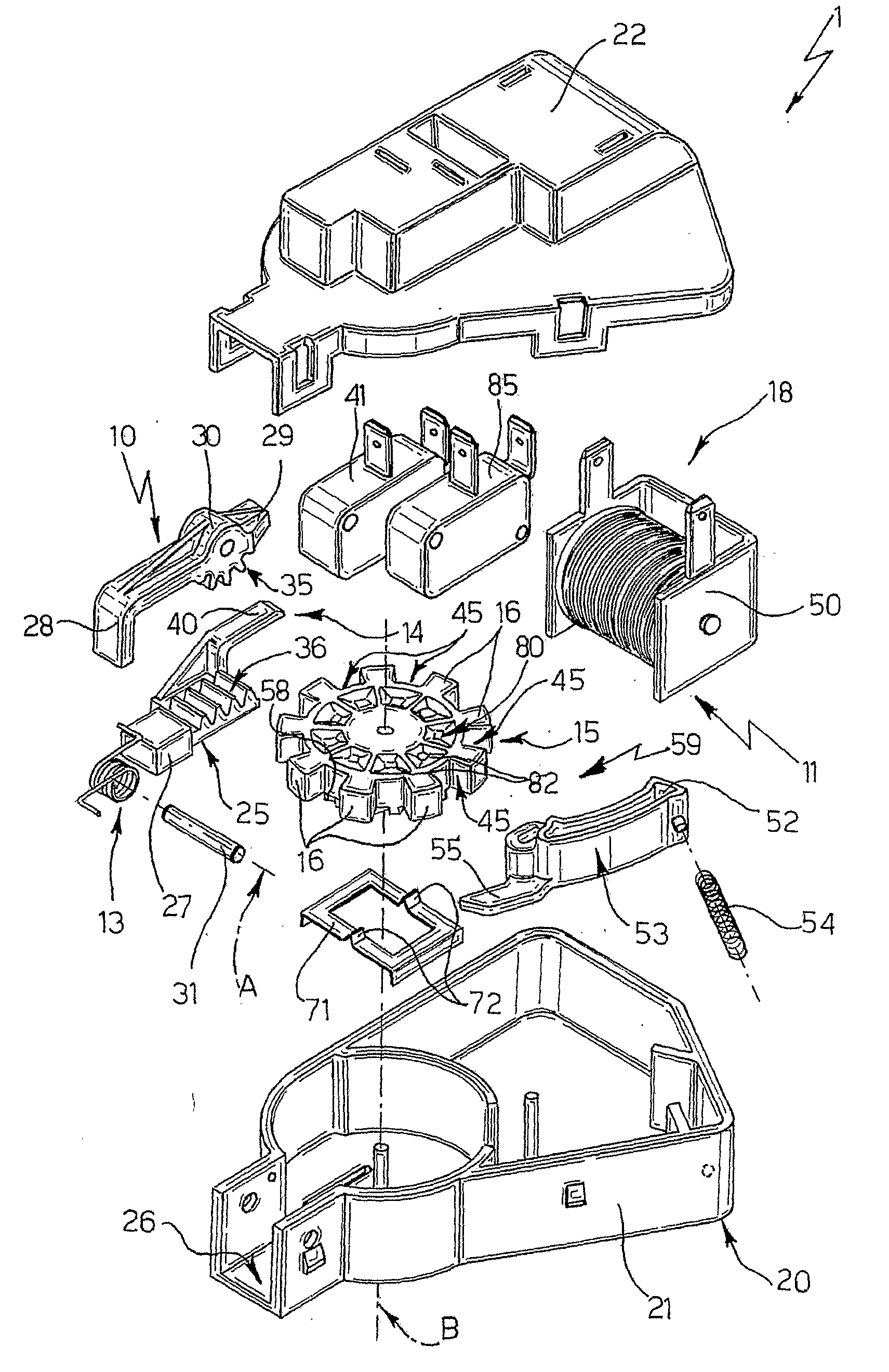
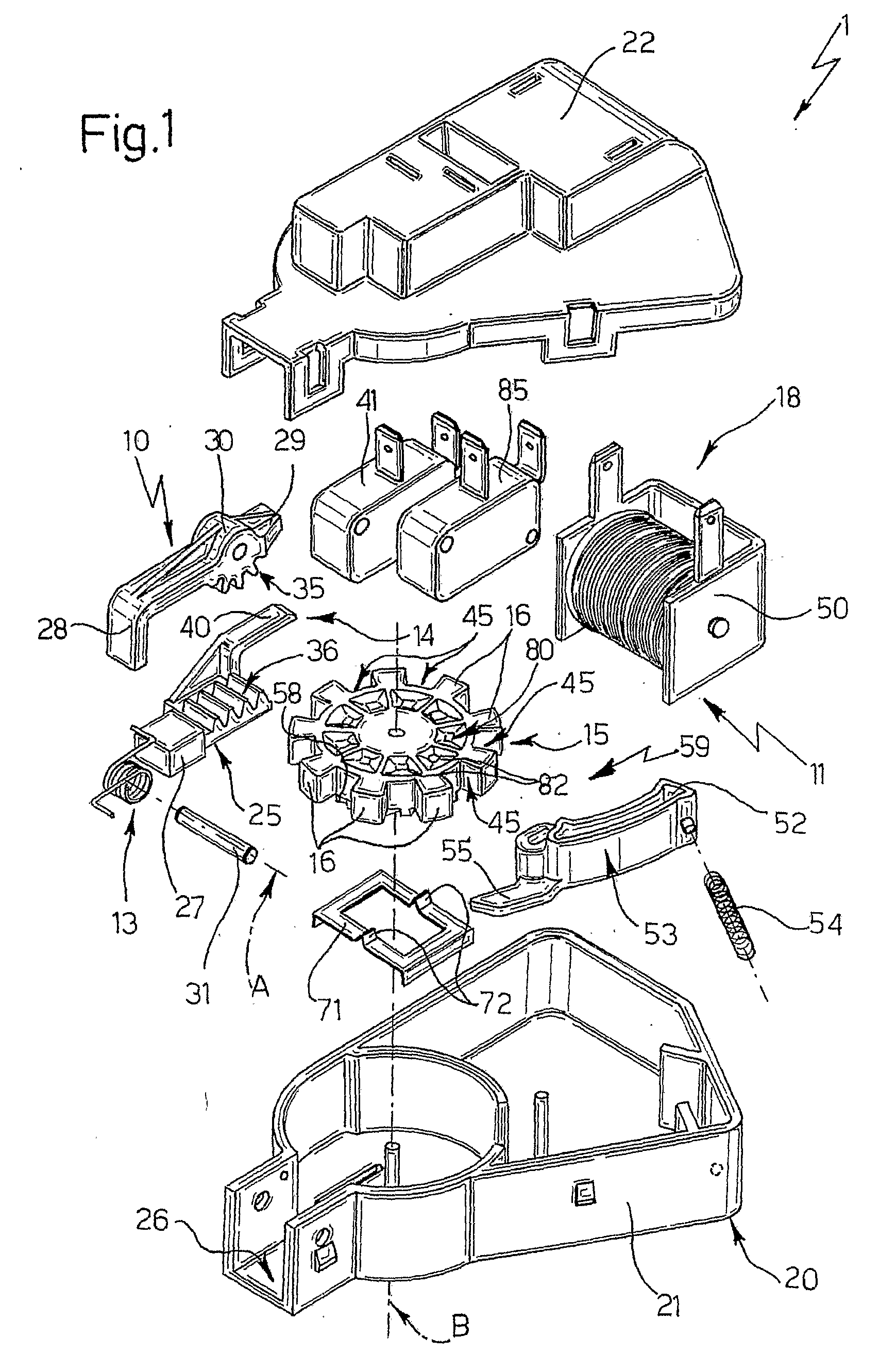
[0015]With reference to FIGS. 1 to 5, number 1 indicates as a whole a blocking device for a door 2 (FIG. 2) of an electric household appliance—in the example shown, a known pyrolytic oven, of which, for the sake of simplicity, is shown only part of a casing 3 defining a door opening 4, against which door 2 rests substantially in fluidtight manner in the closed position (the position shown)

[0016]Door blocking device 1 comprises a retaining member 10 movable, along a given path indicated by arrow T in FIG. 2, between a work position (shown by the continuous line in FIG. 2), in which retaining member 10 cooperates in use with a known coupling member 8 of door 2 when the door is in the closed position shown, and a rest position (shown partly by the dash line in FIG. 2), in which retaining member 10 does not cooperate in use with coupling member 8, by being located, for example, at a distance from coupling member 8 of door 2 in the closed position.

[0017]Device 1 also comprises controlled...


PUM


Abstract

A door blocking device including a retaining member movable, along a given path, between a work position and a rest position, in which it respectively cooperates with and does not cooperate with a coupling member of the door when the door is in a closed position; and controlled-actuation means for controlled actuation of the retaining member, and which include elastic means for pushing the retaining member into the rest position; means for moving the retaining member into the work position in opposition to the elastic means; a rotary member having at least one radially projecting peripheral lobe; and an electrically controlled actuator for moving the rotary member selectively between a first angular position, in which the at least one lobe does not interfere with the given path (T), thus allowing the retaining member to move between the work position and the rest position, and a second angular position, in which the lobe interferes with the given path to lock the retaining member in the work position in opposition to the elastic means.

Description

TECHNICAL FIELD[0001]The present invention relates to a blocking device for the door of an electric household appliance, particularly suitable for locking a pyrolytic oven door in the closed position.BACKGROUND ART[0002]As is known, for safety reasons, the door of numerous types of electric household appliances, such as washing-machines, dishwashers, and pyrolytic ovens, must be locked in the closed position when the appliance is operating, to prevent the user from inadvertently opening the door. Pyrolytic ovens, in particular, in addition to normal cooking cycles, also perform a self-cleaning cycle, in which the oven temperature is much higher than normal (and therefore potentially dangerous to the user) to remove, by pyrolysis, dirt (e.g. grease) particles from the walls of the oven. At least during the self-cleaning cycle, therefore, the oven door must be locked absolutely reliably.[0003]Since known door blocking devices, such as those used on washing-machines and dishwashers, ar...

Claims


Application Information

Patent Timeline
IPC IPC(8): E05C3/36F24C15/00
CPCE05B15/0046E05B15/101E05B17/0033F24C15/022E05B47/0004E05B47/0607E05B47/0002Y10T292/1021Y10T292/1079Y10T292/1082F24C15/02
Inventor CHIRUMBOLO, DINO
Owner ITW IND COMPONENTS SRL
Why Eureka
Try Eureka