Coupling antenna

a coupling antenna and antenna technology, applied in the direction of separate antenna unit combinations, resonant antennas, radiating element structural forms, etc., can solve the problems of low antenna production rate, increased thickness of the whole antenna, and complicated antenna structure, etc., to achieve the effect of improving the operating bandwidth of the coupling antenna

Active Publication Date: 2008-08-21
ADVANCED CONNECTEK INC
View PDF4 Cites 17 Cited by
  • Summary
  • Abstract
  • Description
  • Claims
  • Application Information

AI Technical Summary

Benefits of technology

[0010]A coupling antenna in accordance with the present invention has a ground plane, a main radiating assembly and a secondary radiating assembly. The main radiating assembly is mounted on the ground plane and has a substrate, a feeding-and-coupling assembly and a shorting member. The feeding-and-coupling assembly has a feeding member, a coupling member and an extension member. The second radiating assembly is mounted on the ground plane, is connected to the main radiating assembly and has a first radiating patch and a second radiating patch. With the extension member and the first and second radiating patches, operating bandwidth of the coupling antenna is improved.

Problems solved by technology

However, the complicated structure of the second and third radiating members (150, 170) greatly increases the thickness of the whole antenna.
However, the regulators (REG), grounding member (G), shorting circuit member (ST) on the ground plane (GPN) is too tiny to be stamped so that the production rate of the antenna is low.
Moreover, the regulators (REG) on the ground plane (GPN) further complicate the structure of the antenna and limit the operating bandwidth of the antenna.

Method used


Image

  • Coupling antenna
  • Coupling antenna
  • Coupling antenna

Examples


Embodiment Construction

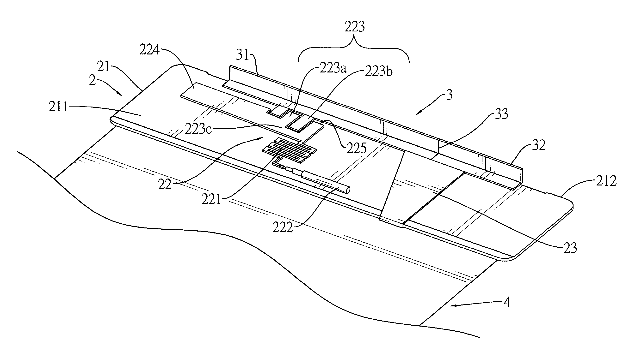
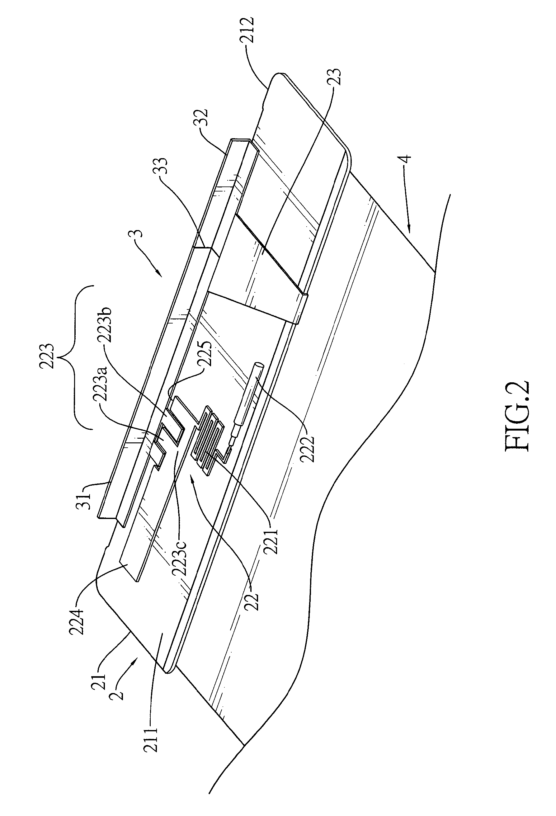
[0018]With reference to FIGS. 2 and 3, a coupling antenna in accordance with the present invention comprises a ground plane (4), a main radiating assembly (2) and a secondary radiating assembly (3).

[0019]The ground plane (4) is made of metal and has a top surface.

[0020]The main radiating assembly (2) is mounted on the ground plane (4) and has a substrate (21), a feeding-and-coupling assembly (22) and a shorting member (23).

[0021]The substrate (21) is made of dielectric member, is mounted on the top surface of the ground plane (4) and has a top surface (211) and a side edge. The length and the width of the substrate (21) are about 84 mm and about 9 mm.

[0022]The feeding-and-coupling assembly (22) is made of metal, is mounted on the top surface (211) of the substrate (21), connected to a feeding cable (222) and has a feeding member (221), a coupling member (223) and an extension member (224).

[0023]The feeding member (221) is zigzag, is mounted on the top surface of the substrate (21), ...


PUM


Abstract

A coupling antenna has a ground plane, a main radiating assembly and a secondary radiating assembly. The main radiating assembly is mounted on the ground plane and has a substrate, a feeding-and-coupling assembly and a shorting member. The feeding-and-coupling assembly has a feeding member, a coupling member and an extension member. The second radiating assembly is mounted on the ground plane, is connected to the main radiating assembly and has a first radiating patch and a second radiating patch. With the extension member and the first and second radiating patches, operating bandwidth of the coupling antenna is improved.

Description

BACKGROUND OF THE INVENTION[0001]1. Field of the Invention[0002]The present invention relates to an antenna, and more particularly to a coupling antenna increasing the operating bandwidth thereof.[0003]2. Description of Related Art[0004]Wireless telecommunication technologies have greatly developed to be mature, reliable and marketable so that the market demand for the wireless products greatly increases in the recent years. Antennas, the most important components in wireless products, are designed to increase the operating bandwidth and reduced the size thereof to make the wireless products have high performance and compact structure.[0005]The telecommunication protocols in different areas are distinct and employ different bandwidths. Therefore, wireless product manufacturers design the wireless products to have modulating functions.[0006]With reference to FIG. 1, a conventional multi-band antenna (100) comprises a ground plane (GPN), a pair of regulators (REG), a shorting member (...

Claims


Application Information

Patent Timeline
Patent Type & Authority Applications(United States)
IPC IPC(8): H01Q1/38H01Q1/50H01Q5/15
CPCH01Q1/243H01Q1/38H01Q21/30H01Q9/0421H01Q1/50
Inventor LIN, SHENG-CHIHTSENG, YI-WEICHIU, TSUNG-WENHSIAO, FU-REN
Owner ADVANCED CONNECTEK INC
Why Eureka
Try Eureka