Lighting Device

a technology of lighting devices and light sources, applied in lighting and heating apparatus, identification means, instruments, etc., can solve the problems of low light output resolution, complicated arrangement, and marked deterioration of the intended function of lighting devices, so as to reduce the risk of mechanical wear, less complex, and less complicated

Inactive Publication Date: 2008-08-21
KONINKLIJKE PHILIPS ELECTRONICS NV
View PDF4 Cites 18 Cited by
  • Summary
  • Abstract
  • Description
  • Claims
  • Application Information

AI Technical Summary

Benefits of technology

[0004]It is therefore an object of the present invention to provide a lighting device of the type described in the opening p

Problems solved by technology

However, such an arrangement may be quite complex, and the light output resolution is low as compared with the resolution of e.g. an LCD panel.
In addition, it has been found that the repeated motion of a moveable foil to and

Method used


Image

  • Lighting Device
  • Lighting Device
  • Lighting Device

Examples


first embodiment

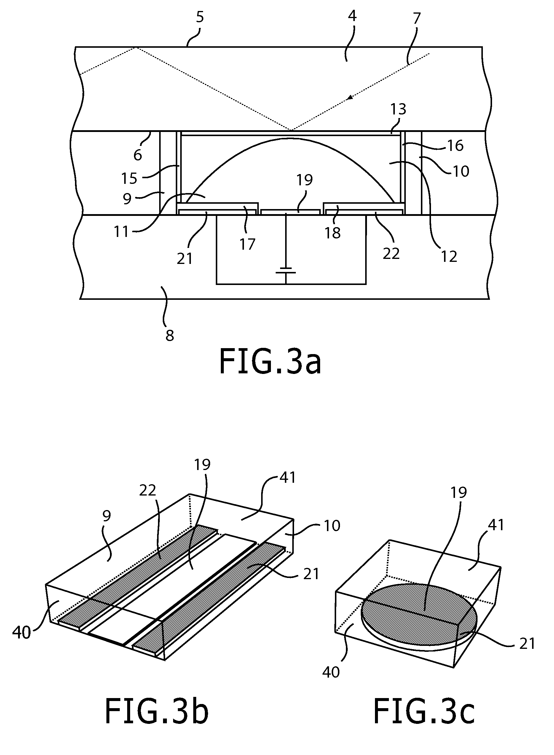
[0036]FIG. 3b is a perspective view of a cell layout in a The lateral wall parts 9, 10 are covered by a hydrophobic material, but the front and back wall parts 40, 41 (as seen in the drawing) are moderately hydrophilic, such that the liquid (not shown) will at least partially wet these walls. The hydrophilic electrode 19 on the support plate covers a trace between the front and back wall parts 40, 41. The liquid will therefore have the shape of a cylindrical cap, similar to that of a cylindrical convex lens.

second embodiment

[0037]FIG. 3c is a perspective view of a cell layout in a Both the lateral wall parts and the front and back wall parts 40, 41 have hydrophobic coatings. The hydrophilic surface of the electrode 19 on the support plate is confined to the center of the cell, and the electrode 21 (only one buried electrode needed in this case) surrounds this area. In this alternative, the liquid will approximately have the shape of a spherical cap.

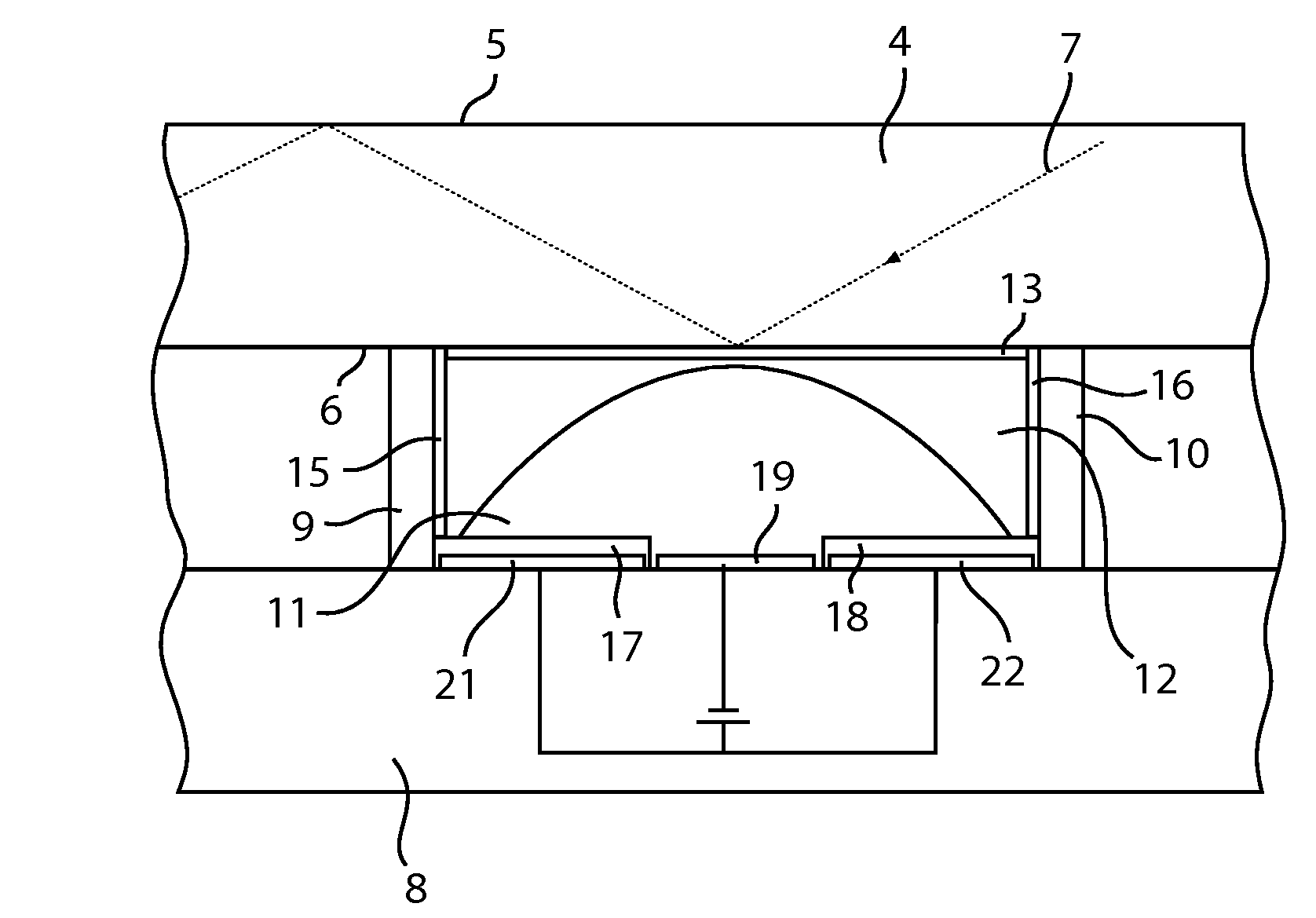
[0038]FIG. 4 illustrates in a cross-section out-coupling arrangements in three different states. A cell in a first state is illustrated at 25. In this cell 25, a zero voltage difference, V0=0 V, is applied between the liquid 11 in the cell and the electrodes 21, 22. In this state, the liquid wets the structured hydrophobic coating on the support plate 8 to only a very limited extent, and the liquid quantity thus has a maximal curvature, i.e. the contact angle θ between the liquid and the support plate, as measured outside the liquid, is relatively small. Th...


PUM


Abstract

The present invention relates to a lighting device wherein an in-coupled light flow is at least partly constrained within a light-guide plate (4) by means of total internal reflection. The device includes means for achieving a selective local light output from the output surface (6) of the light-guide plate, such that the intensity of the emitted light flow from the light guide can be locally controlled over its output surface area. This is achieved by a number of closed cells adjoining the output surface. Each cell contains a liquid element (11), the form of which may be manipulated by electrowetting, such that the liquid can be brought to a greater or lesser extent into optical contact or out of optical contact with a local area of the output surface (6), thereby varying the intensity of the locally out-coupled light flow therethrough. The cell may be built up by the light-guide plate (4), a support plate (8) and lateral wall parts (9,10). The support plate (8) may consist of a hydrophobized glass plate, which is positioned parallel to the light-guide plate (4).

Description

FIELD OF THE INVENTION[0001]The present invention relates to a lighting device comprising a light-guide plate, said light-guide plate having first and second main surfaces and being arranged to receive light from at least one light source and to at least partly constrain the light therein by total internal reflection, and at least one local out-coupling device being arranged to selectively extract light from a local area of said second main surface by reducing the index of refraction drop at said local area.BACKGROUND OF THE INVENTION[0002]Such a lighting device comprising a moveable light-scattering foil is disclosed in e.g. WO A1 2004 / 027468. The moveable foil can be made by applying a voltage-induced electrostatic force, either to locally contact the second main surface in order to locally extract light therefrom, or it can be made to locally remain out of contact with the second main surface so that no light is locally extracted. The arrangement with the moveable foil allows the...

Claims


Application Information

Patent Timeline
IPC IPC(8): G02F1/13357F21V8/00
CPCG02B26/004G02B6/0033G02B6/00G02B26/02G02F1/1335G09F9/37
Inventor MARRA, JOHANDE BOER, DIRK KORNELIS GERHARDUS
Owner KONINKLIJKE PHILIPS ELECTRONICS NV
Why Eureka
Try Eureka