Interface Method Between Remote Radio Unit And Centralized Transceiver Station

a technology of remote radio and centralized radio, applied in the field of base transceiver station technology, can solve the problems of reducing the management and maintenance operation needed for signal transmission and networking cos

Inactive Publication Date: 2008-08-21
UTSTARCOM TELECOM CO LTD
View PDF9 Cites 72 Cited by
  • Summary
  • Abstract
  • Description
  • Claims
  • Application Information

AI Technical Summary

Benefits of technology

[0017]The invention will be better understood when reading the preferred embodiments of the invention in conjunction with accompanying drawings, therefore the benefits, features, and advantageous effects of the present invention will become more evident, wherein:
[0018]FIG. 1A schematically shows the structure of a wireless access network in a conventional mobile communication system;
[0019]FIG. 1B schematically shows the basic structure of a BTS system in the conventional mobile communication system;
[0020]FIG. 2 schematically shows the structure of a CBTS system using RRH technology;
[0021]FIG. 3 schematically shows a GFP-T frame structure for block code character stream according to GFP;
[0022]FIG. 4 schematically shows the structure of the interface between a RRU and a central channel processing main unit according to a preferred embodiment of the present invention;

Problems solved by technology

The method directly uses mature Synchronous Digital Hierarchy (SDH) / Optical Transmission Network (OTN) Transmission network technology to realize digital wireless signal transmission between RRU and main BTS without the need for specific transmission technology, therefore further reduces the management and maintenance operation needed for signal transmission as well as networking cost.

Method used


Image

  • Interface Method Between Remote Radio Unit And Centralized Transceiver Station
  • Interface Method Between Remote Radio Unit And Centralized Transceiver Station
  • Interface Method Between Remote Radio Unit And Centralized Transceiver Station

Examples


Embodiment Construction

[0031]The objectives, benefits, and advantageous effects of the present invention, will be more clearly understood from the following detailed description of the invention taken in conjunction with the accompanying drawings.

[0032]1. Wireless Signal Transmission and RRU-MU Interface Protocol

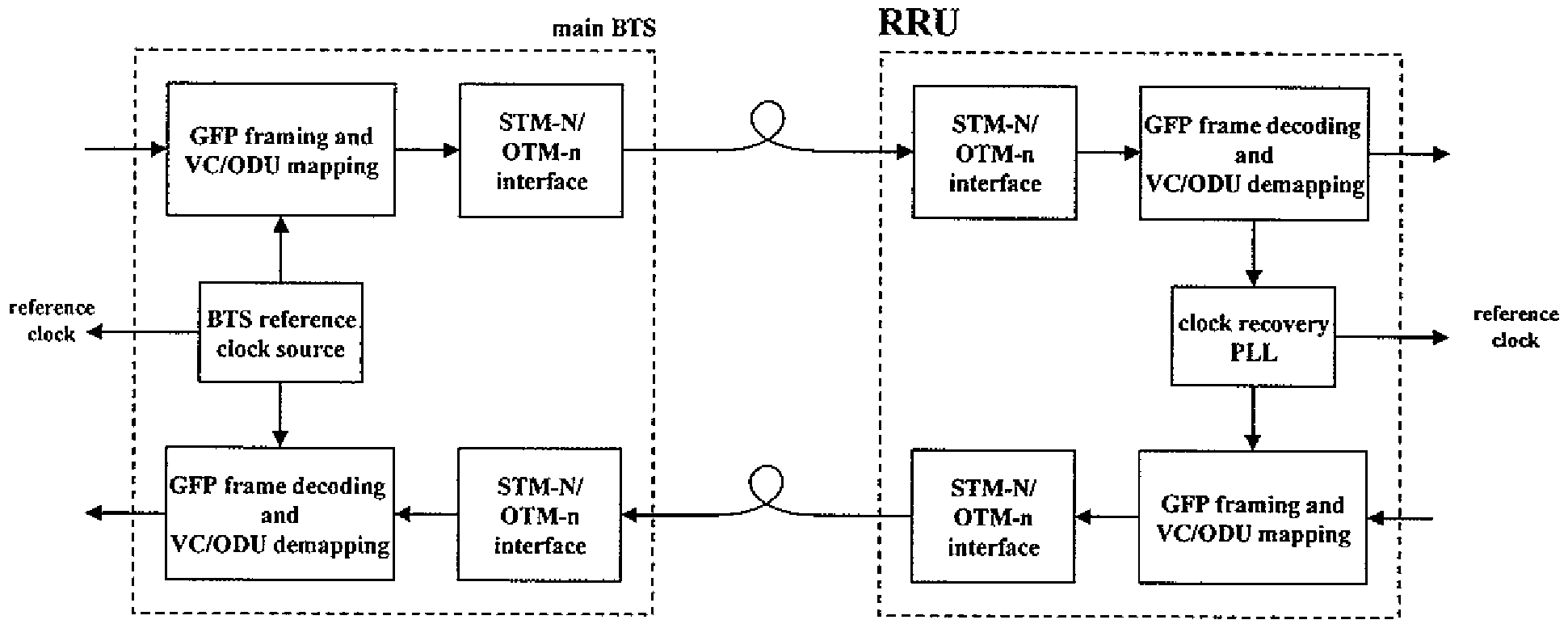
[0033]FIG. 4 shows the structure of the RRU-MU interface protocol according to the present invention. The interface is composed of user plane and control plane. Wherein the user plane mainly carries the I / Q sampling data concerning the user data. The I / Q sampling data are firstly formed into I / Q data frame via an I / Q data frame adaptation layer, and then transmitted on SDH / OTN via GFP-T. The control signaling of the control plane is carried on UDP (User Data Protocol) / IP and / or TCP (Transmission Control Protocol) / IP, and IP packet is carried on PPP and formed into a frame by HDLC (High-Level Data Link Control). At last the HDLC frame including the control plane signaling is transmitted on SDH / OTN ...


PUM


Abstract

The present invention discloses a method for transmitting signal between a central channel processing Main Unit (MU) and one or more Remote Radio Units (RRUs) by using SDH / OTN in Centralized Base Transceiver Station system using remote radio head (RRH) technology. The method includes: dividing the communication interface between the MU and the RRUs into a user plane and a control plane, the user plane mainly for carrying I / Q sampling data concerning the user data, and the control plane mainly for carrying the data concerning control signaling; forming the I / Q sampling data concerning the user data carried by the user plane into an I / Q data frame via an I / Q data frame adaptation layer, then forming the I / Q data frame into a GFP frame via GFP and transmitting it on SDH / OTN; and carrying the control signaling of the control plane on UDP / IP and / or TCP / IP, and further carrying IP packet on PPP and forming it into a frame by HDLC, transmitting the HDLC frame including the control plane signaling on the SDH / OTN via the control character channel of the GFP frame. According to the present invention, the existing SDH / OTN transmission network is utilized directly, which further reduces the management and maintenance operation needed for signal transmission, as well as networking cost.

Description

FIELD OF THE INVENTION[0001]The present invention relates to a Base Transceiver Station technology used in mobile communication system, and more particularly, to an interface method between Remote Radio Unit and Centralized Radio Base Station in Centralized Base Transceiver Station system using Remote Radio Head (RRH) technology.BACKGROUND OF THE INVENTION[0002]1. Centralized Base Transceiver Station (CBTS) and Wireless Signal Transmission[0003]As illustrated in FIG. 1A, in mobile communication systems, wireless access network is typically composed of Base Transceiver Stations (BTSs) and Base Station Controllers (BSCs) or Radio Network Controllers (RNCs) for controlling a plurality of BTSs, wherein the BSC is mainly composed of a base band processing subsystem, a radio frequency (RF) subsystem, and an antenna etc, which is responsible for transmitting, receiving, and processing wireless signal, a BTS can cover various cells by means of a plurality of antennas, as illustrated in FIG....

Claims


Application Information

Patent Timeline
Patent Type & Authority Applications(United States)
IPC IPC(8): H04J14/08H04W88/08H04W92/10
CPCH04J3/1617H04W88/085H04J2203/0035H04J3/1658H04J3/0682
Inventor LIU, SHENGLI, YULIN
Owner UTSTARCOM TELECOM CO LTD
Why Eureka
Try Eureka