Orthodontic bracket

a technology for orthodontic brackets and brackets, applied in the field of orthodontic brackets, can solve the problems of only being able to apply wires with a sufficient diameter, affecting the effect of intended correction, etc., and achieve the effect of optimal fixation and increased resistan

Inactive Publication Date: 2008-08-21
JAHN INGOLF
View PDF18 Cites 13 Cited by
  • Summary
  • Abstract
  • Description
  • Claims
  • Application Information

AI Technical Summary

Benefits of technology

[0017]A variation of the invention includes self-securing insertion slots on the outer surface of the bracket which accommodate an appropriately formed bend in the surface of the spring. This increases the resistance counteracting any unintentional displacement of the treatment wire from the slot.
[0018]An additional feature of the invention relates to the form of the cross section of the archwire that runs parallel to the inner surface of the slot while the upper surface of the arch-shaped wire is rounded. The advant

Problems solved by technology

Anchorage of the archwire using this method has disadvantages as it is difficult to achieve the optimal dosage of pressure needed for each individual tooth,

Method used


Image

  • Orthodontic bracket
  • Orthodontic bracket
  • Orthodontic bracket

Examples


Embodiment Construction

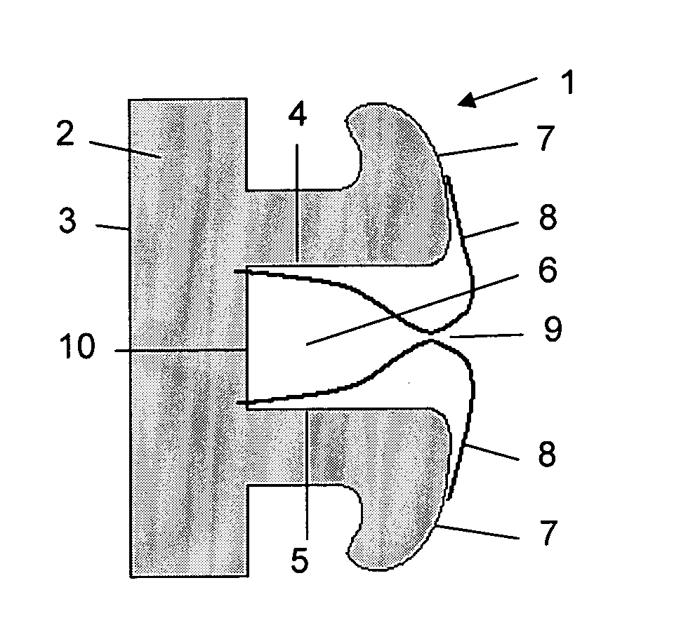
[0026]The bracket consists—as FIG. 1 shows—of a cubed-shaped body (1) the basis (2) of which is fixed, usually using adhesive via the lower surface (3) to a tooth which is not shown on the drawing. On the basis (2) are two fixed positioned parallel running side walls (4, 5) that form a slot (6).

[0027]The brackets positioned on the row of teeth have a row of slots (6) forming a continual groove (not illustrated). The side walls (4, 5) of the slots (6) are constructed to form out pointing right-angles at their opposing free ends and offer there rounded application surfaces (7) for two identical leave-shaped springs (8). From these application surfaces (7) the two springs (8) are curved forward to the middle of the archwire slot (6) and to a wedge-shaped gap (9). From the gap (9) the distance between the springs (8) and the neighbouring side walls (4, 5) is continually reduced but without these making contact. The springs (8) are secured on the floor (10) of the slot (6).
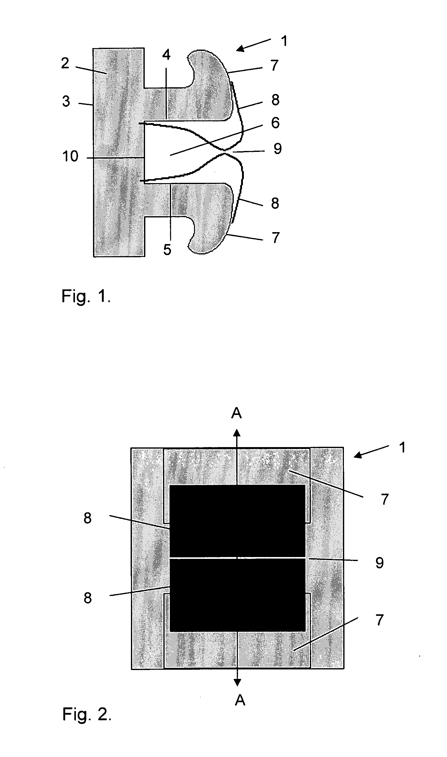
[0028]FIG. 2 s...


PUM


Abstract

In a cube-shaped Bracket the underside of which is attached to a tooth and with a slot in the upper surface forming together with the neighbouring teeth a continual groove an elastic element is incorporated in the slot which is a pair of leaf-shaped springs an archwire can be securely fixed between.

Description

[0001]This claims priority to German patent application DE 10 2007 008 356.6, filed Feb. 20, 2007, the entire disclosure of which is incorporated by reference herein.[0002]Orthodontic brackets are familiar as holding / fixing devices with which a wire that describes the ideal arch of a row of teeth is held in place. Via the brackets pressure is applied to the individual teeth that do not correspond to this ideal arch thus helping to correct the faulty position.[0003]As the pressure applied to the teeth cannot be too intense, the strength of the wire is increased step by step. The archwire must be replaced several times during the treatment.BACKGROUND[0004]Usually a bracket consists of a metal cube that is fixed on its under side to the outer surface of the teeth. The upper surface of the bracket has a slot which corresponds to the slot in the neighbouring brackets and forms a continual groove.[0005]The cross section of the groove into which the archwire is fitted is generally a right-...

Claims


Application Information

Patent Timeline
IPC IPC(8): A61C7/30
CPCA61C7/30A61C7/20
Inventor JAHN, INGOLF
Owner JAHN INGOLF
Why Eureka
Try Eureka