

Box vane mixing element for automotive heating, ventilating and air conditioning system
- Summary
- Abstract
- Description
- Claims
- Application Information
AI Technical Summary
Benefits of technology
Problems solved by technology
Method used
Image

Examples
Embodiment Construction
[0032]The present invention is intended for application in automotive vehicle applications and will be described in that context. It is to be understood, however, that the present invention could also be successfully applied in many other applications. Accordingly, the claims herein should not be deemed limited to the specifics of the preferred and alternative embodiments of the invention described hereunder.
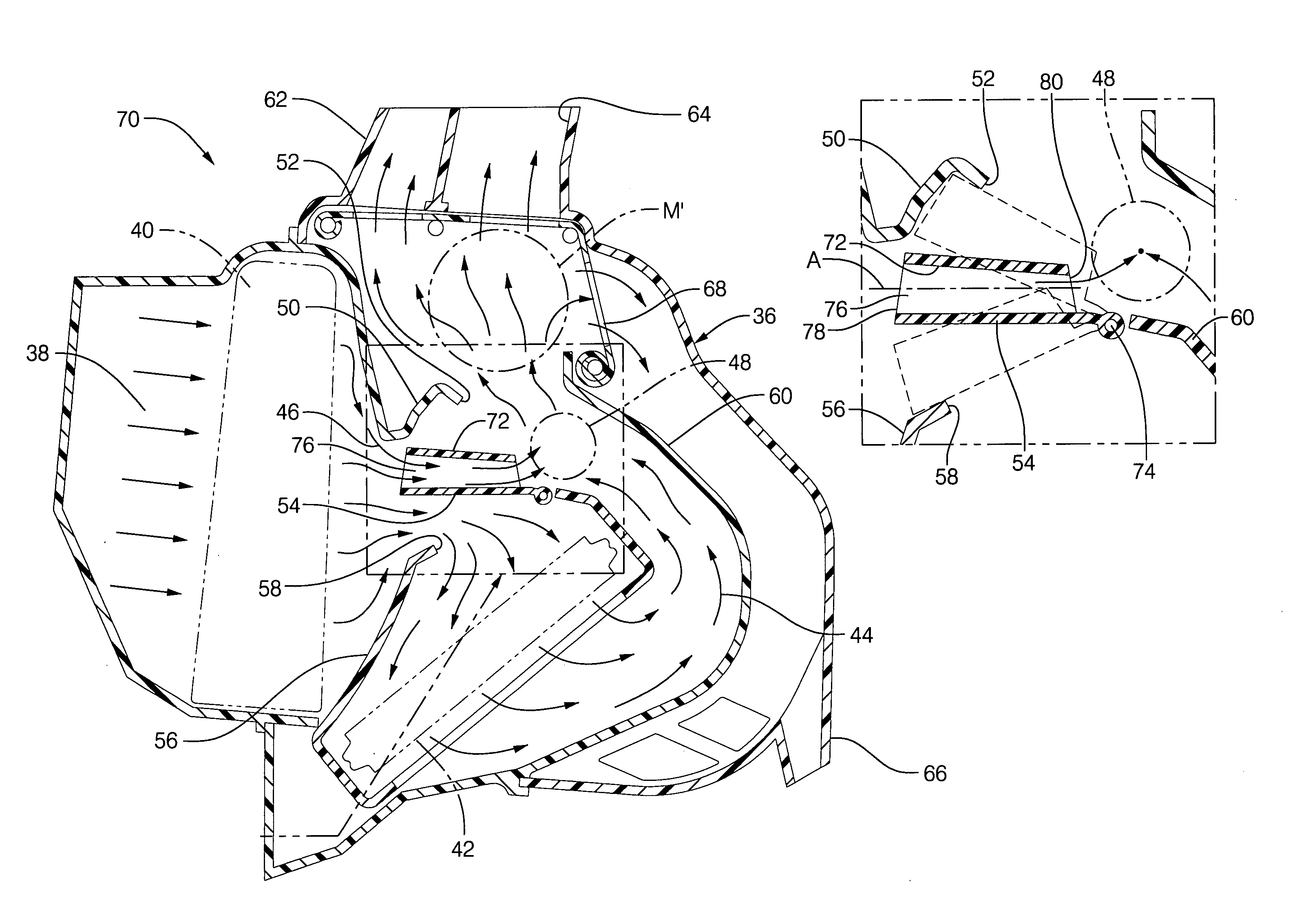
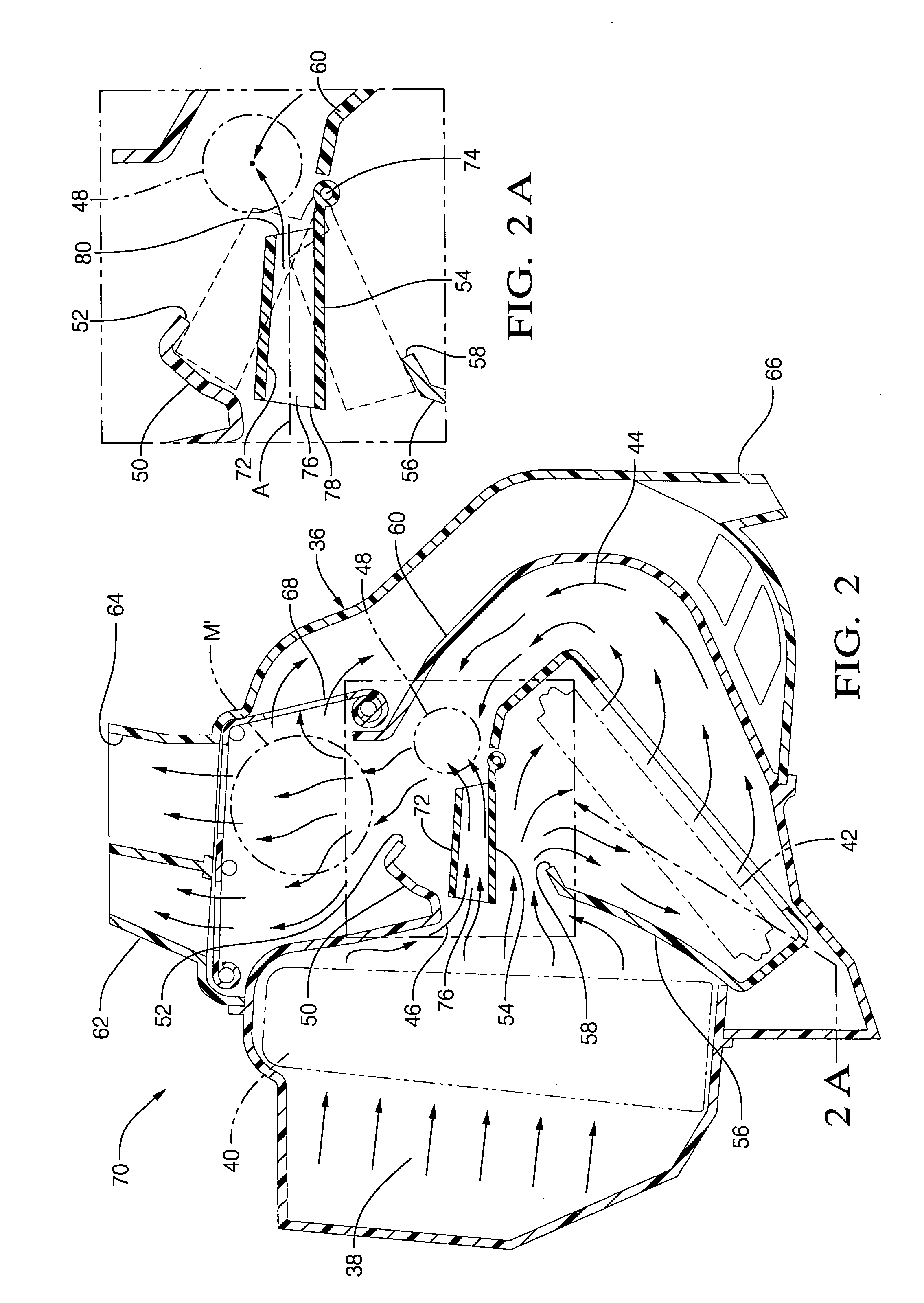
[0033]Referring to FIGS. 2 and 2A, a HVAC housing, indicated generally at 36, is a large hollow box, generally a multi-piece unit built up out of two or more molded plastic sub-sections. A non-illustrated blower and scroll housing draw ambient or inlet air 38 and force it through the housing 36, first through an evaporator 40, through which the entire air flow 38 initially passes, and then toward a heater core 42. While the evaporator 40 always has air flow through it, it may or may not be active and cold, depending on whether the associated compressor (non-illustrated) is activ...
PUM
 Abstract
Description
Claims
Application Information