Transmitter

a technology of transmitters and transmitters, applied in the field of transmitters for mobile communication systems, can solve the problems of distortion, significant degraded signal quality, and reduced power amplifier cost, and achieve the effect of high signal quality and suppression of unfavorable peak level

Inactive Publication Date: 2008-08-21
KOKUSA ELECTRIC CO LTD
View PDF3 Cites 19 Cited by
  • Summary
  • Abstract
  • Description
  • Claims
  • Application Information

AI Technical Summary

Benefits of technology

[0085]As described thus far, according to the present invention, in consideration of levels of respective carrier signals contained in a multi-carrier signal serving as an object for peak level suppression, the peak level of the multi-carrier signal is suppressed, thus allowing favorable peak level suppression to be performed. For example, in detecting and suppressing the peak power of a multi-carrier transmission signal, it is possible to maintain a high signal quality for any transmission signal pattern.

Problems solved by technology

These examples of problems can occur by multi-carrier transmission of two or more carriers.
Furthermore, if the PAPR of an input signal of a power amplifier is low, a power amplifier with a low saturation level can accordingly be used, which leads to the cost reduction of the power amplifier.
However, if a level difference exists between carriers in multi-carrier transmission as mentioned above, there have been caused problems that signal quality is significantly degraded and distortion is found in a burst interval.
Therefore, in the case where a level difference exists in a transmission carrier signal or in the case of a burst signal in which a carrier during an interval is not transmitted, there have been caused problems that the level of the peak power suppression signal becomes high with respect to the carrier signal, and radio specification cannot be satisfied.

Method used


Image

  • Transmitter
  • Transmitter
  • Transmitter

Examples


embodiment 1

[0110]A first embodiment of the present invention will be described below.

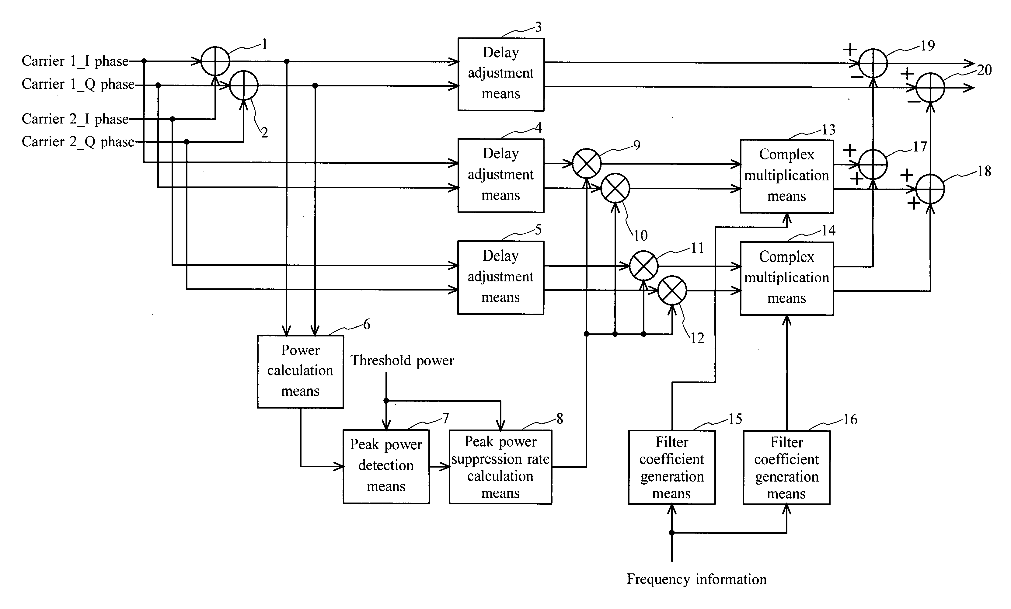
[0111]FIG. 1 shows an exemplary configuration of a peak power suppression means provided in a transmitter according to a first embodiment of the present invention.

[0112]The peak power suppression means of the present embodiment includes: adders 1, 2; delay adjustment means 3, 4, 5; a power calculation means 6; a peak power detection means 7; a peak power suppression rate calculation means 8; multipliers 9, 10, 11, 12; complex multiplication means 13, 14; filter coefficient generation means 15, 16; adders 17, 18; and subtracters 19, 20.

[0113]An exemplary operation performed in the peak power suppression means of the present embodiment will be described below.

[0114]In the present embodiment, there is shown a case where two carriers 1, 2 are used as a plurality of carriers.

[0115]The adder 1 adds and synthesizes I phases of respective input carrier signals, and outputs the resultant I phase component of a multi-ca...

embodiment 2

[0148]A second embodiment of the present invention will be described below.

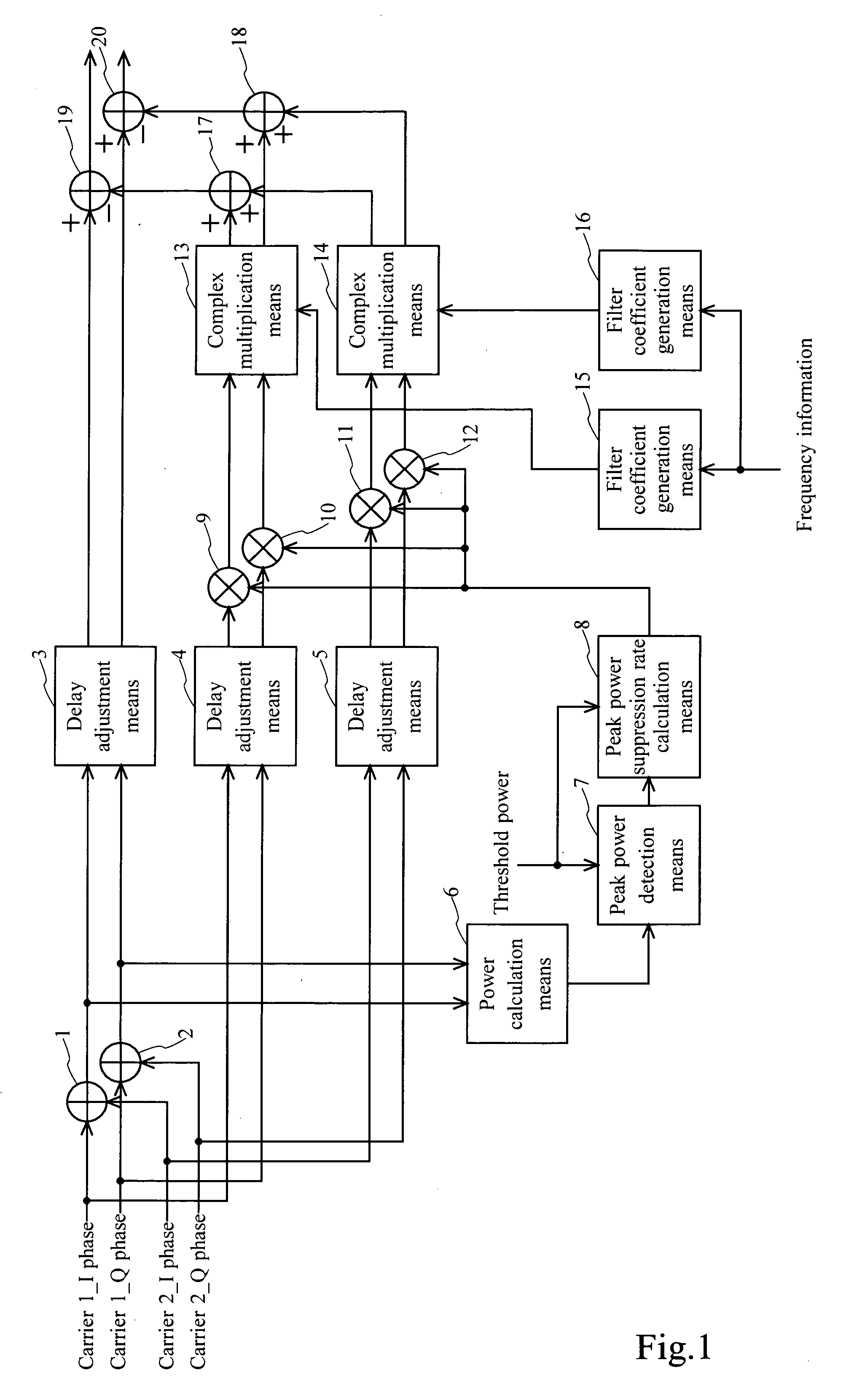
[0149]FIG. 2 shows an exemplary configuration of a peak power suppression means provided in a transmitter according to the second embodiment of the present invention.

[0150]The peak power suppression means of the present embodiment includes: delay adjustment means 31, 32, 33; a power calculation means 34; a peak power detection means 35; a peak power suppression rate calculation means 36; multipliers 37, 38, 39, 40; complex multiplication means 41, 42; filter coefficient generation means 43, 44; adders 45, 46; and subtracters 47, 48.

[0151]In this embodiment, the configuration and operation of the peak power suppression means shown in FIG. 2 are similar to those of the peak power suppression means shown in FIG. 1 except that carrier signals (carriers 1 and 2) and a signal (synthesized signal) produced by multi-carrier synthesis of the carrier signals are provided as input signals. And respective processing part...

embodiment 3

[0154]A third embodiment of the present invention will be described below.

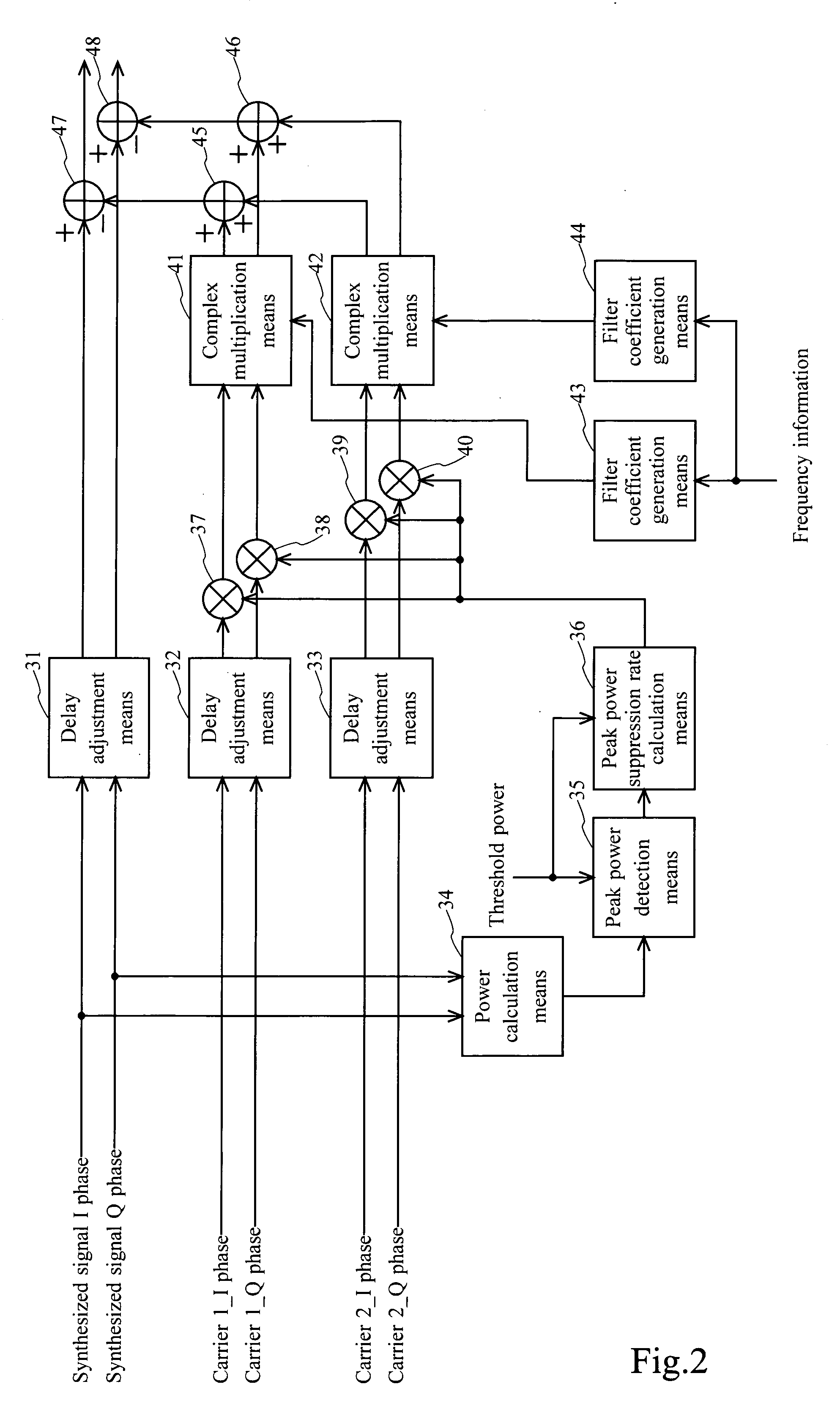
[0155]FIG. 3 shows an exemplary configuration of a peak power suppression means provided in a transmitter according to the third embodiment of the present invention.

[0156]The peak power suppression means of the present embodiment includes: delay adjustment means 51, 52; a power calculation means 53; a peak power detection means 54; a peak power suppression rate calculation means 55; multipliers 56, 57; a complex multiplication means 58; a filter coefficient generation means 59; subtracters 60, 61; and a carrier power detection means 62.

[0157]In this embodiment, the delay adjustment means 51, 52, the power calculation means 53, the peak power detection means 54, the peak power suppression rate calculation means 55, the multipliers 56, 57, the complex multiplication means 58, and the subtracters 60, 61 are operated similarly to the respective processing parts 311 to 317, and 319 of the peak power suppression mea...


PUM


Abstract

In a transmitter that suppresses the peak level of a multi-carrier signal produced by synthesizing a plurality of carrier signals, high signal quality is maintained for any transmission signal pattern, for example. In a peak power suppression means shown in the drawings, suppression signal generation means 7 to 18 generate a peak level suppression signal having a level according to levels of respective carrier signals for frequencies of the respective carrier signals contained in the multi-carrier signal. Suppression signal subtraction means 19, 20 subtract, from the multi-carrier signal, the peak level suppression signal generated by the suppression signal generation means 7 to 18.

Description

BACKGROUND OF THE INVENTION[0001]1. Field of the Invention[0002]The present invention relates to transmitters for mobile communication systems, in which methods such as W-CDMA (Wideband-Code Division Multiple Access) and / or OFDM (Orthogonal Frequency Division Multiplexing), for example, are / is used, and in particular relates to a transmitter that detects and suppresses the peak power of a multi-carrier transmission signal.[0003]2. Description of the Background Art[0004]FIG. 16 shows an example of an internal configuration of a peak power suppression means 301.[0005]As shown in Eq. (1), for example, a power calculation means 313 calculates, from I-phase (In-phase) and Q-phase (Quadrature-phase) components of an input signal, an instantaneous power value for each sample.Instantaneous Power=(I-Phase Component)2+(Q-Phase Component)2   Eq. (1)[0006]A peak power detection means 314 compares a power value of an input signal with a threshold power for each sample to determine, as a peak pow...

Claims


Application Information

Patent Timeline
Patent Type & Authority Applications(United States)
IPC IPC(8): H04B1/68H04B1/69H04B1/707H04J11/00
CPCH04B1/707H04L27/2624H04B2201/70706
Inventor OKADA, TAKASHIWATANABE, JUNTODATE, TAKAHIROHASEGAWA, NORIO
Owner KOKUSA ELECTRIC CO LTD
Why Eureka
Try Eureka