

Endoscope system
a technology of endoscope and endoscope, which is applied in the field of endoscope, can solve the problems of deteriorating image generation, no specific or effective configuration to clean the tip end surface of the confocal endomicroscope system, and achieve the effect of effective cleaning
- Summary
- Abstract
- Description
- Claims
- Application Information
AI Technical Summary
Benefits of technology
Problems solved by technology
Method used
Image

Examples
first embodiment
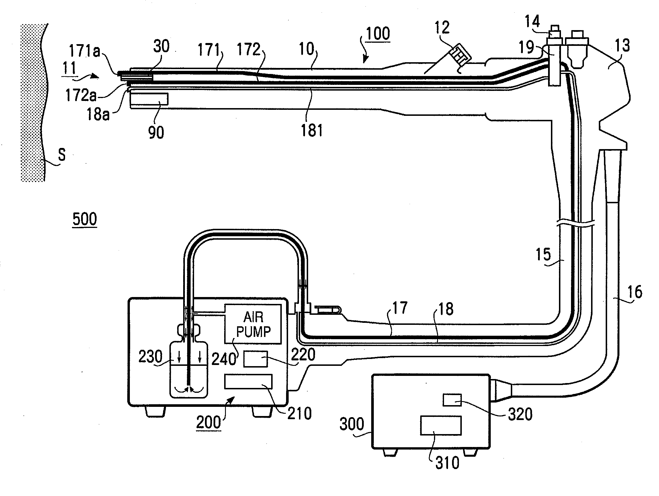
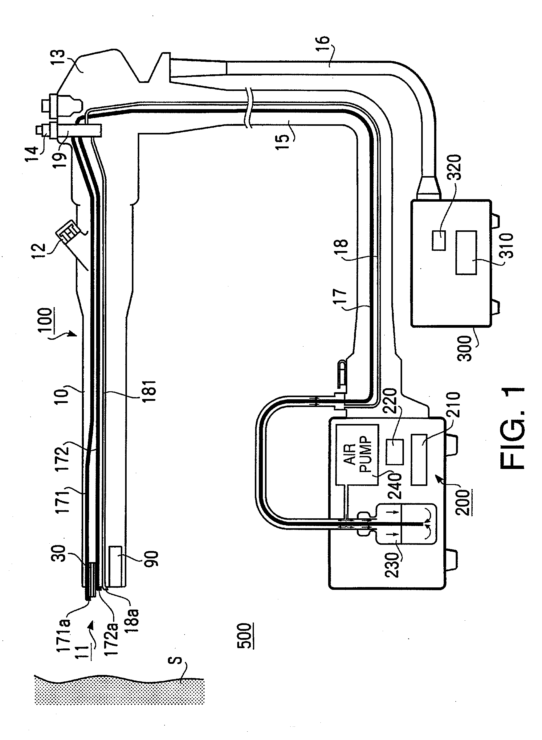
[0028]Hereinafter, referring to the accompanying drawings, an illustrative embodiment of the invention will be described. FIG. 1 is a diagram to schematically illustrate a cross-sectional side view of a confocal endomicroscope system 500 according to the present invention. The confocal endomicroscope system 500 includes an electronic endoscope 100 to be inserted into a body cavity to capture images inside the body cavity, a first processor 200 and a second processor 300 to be respectively connected with the electronic endoscope 100. Each of the processors 200, 300 is connected with a monitor (not shown) to display the images output through the processors 200, 300.
[0029]The first processor 200, which is generally used for conventional observation, includes an image processing unit 210, a conventional light source unit 220, a reservoir 230, and an air pump 240. The second processor 300, which is used for confocal observation, includes an image processing unit 310 and a laser light sou...
second embodiment
[0057]Further, the nozzle portion 171a may not be necessarily shifted along the guide 171f by the expanding force of the helical extension spring 171e as long as the nozzle portion 171a can be protruded outward from the front end surface 30a during the cleaning operation and retracted to be stored in the distal end portion 11 when the confocal optical system 30 is in direct contact with the body tissue S during the observation. An example of such a configuration is shown in FIGS. 5A and 5B as the present invention.
[0058]FIGS. 5A and 5B schematically illustrate a configuration of a nozzle portion 171a′ according to the second embodiment of the present invention.
[0059]According to the second embodiment, the nozzle portion 171a′ includes a resilient tip end portion 171g made of, for example, rubber to form the discharge portion 171b. When water is not fed in the nozzle portion 171a′, as shown in FIG. 5A, the tip end portion 171g closes the opening, and the front end of the nozzle porti...
PUM
 Abstract
Description
Claims
Application Information