Shaped top pin for bump resistant cylinder

a top pin and cylinder technology, applied in the field of cylinder locks, can solve the problems of compromising the security of locks, cylinder locks are vulnerable to many methods of unauthorized manipulation, and the cylinder lock industry is a grave danger to the public, so as to minimize or prevent the opening of the lock by bumping, the effect of improving the bump resistant cylinder lock

Active Publication Date: 2008-08-28
SARGENT MANUFACTURING CO INC
View PDF20 Cites 18 Cited by
  • Summary
  • Abstract
  • Description
  • Claims
  • Application Information

AI Technical Summary

Benefits of technology

[0014]It is another object of the present invention to provide an improved bump resistant cylinder lock utilizing driver pins which are specially designed in a shaped pin configuration and correlated in size to the smallest possible distance between bottom pins and the shear line which occurs when the largest possible stack height of the tumbler pins is in the plug with the bump key inserted. This is an important aspect of the invention to minimize or prevent opening of the lock by bumping.
[0015]It is another object of the invention to provide a method for retrofitting existing cylinder locks which method can be easily performed by locksmiths or owners of the locks.

Problems solved by technology

Cylinder locks are vulnerable to many methods of unauthorized manipulation, including the Bump or Bumpkey method.
This new development compromises lock security and poses a grave danger to the public and a challenge to the cylinder lock industry.
Every commercial location and every consumer can potentially be the victim of a technique of opening locks known as bumping.
If they use conventional pin tumbler cylinders where they live, work, or transact business, then they may be at risk.
The critical issue is the ability to obtain a key that fits the target lock.
If that challenge is met, then virtually all conventional pin tumbler cylinder locks are at risk.
Bumping occurs as the result of an inherent design issue within all conventional pin tumbler locks and is based upon a law of physics of impact and momentum where the impacted tumbler pin will remain in place and the driver pins in contact with the tumbler pins will be pushed upward by the impact energy.
If torque is applied during this brief interval, there is nothing to stop the plug from turning.

Method used


Image

  • Shaped top pin for bump resistant cylinder
  • Shaped top pin for bump resistant cylinder
  • Shaped top pin for bump resistant cylinder

Examples


Embodiment Construction

)

[0045]In describing the preferred embodiment of the present invention, reference will be made herein to FIGS. 1-8 of the drawings in which like numerals refer to like features of the invention.

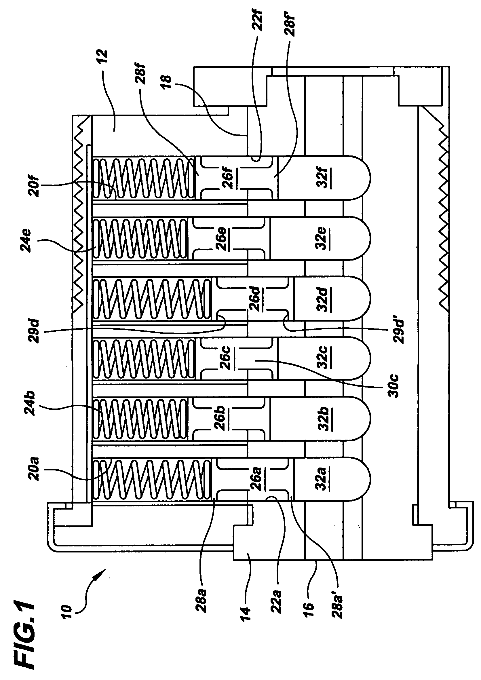
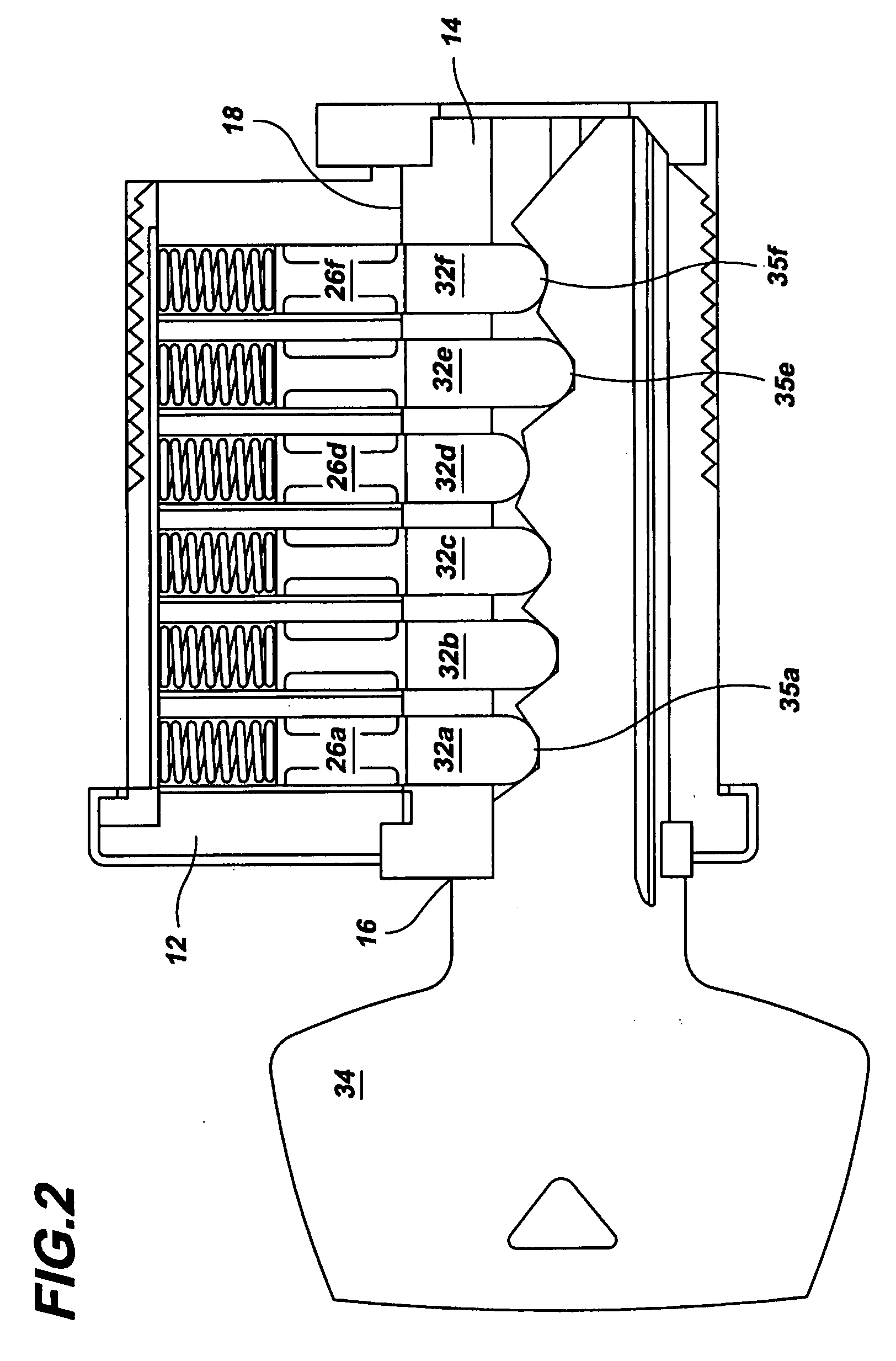
[0046]Referring now to FIG. 1 a conventional tumbler and pin cylinder lock is shown generally as numeral 10. The cylinder lock 10 includes a cylinder portion 12 and a plug portion 14 adapted for rotation therein. The cylinder portion 12 contains a plurality of axially displaced radially disposed bores 20a-20f. The plug portion includes a similar plurality of bores which are aligned and registered with the cylinder bores when the lock is in its closed or rest position. These plug bores are illustrated as 22a-22f and each pair of associated bores in the cylinder and plug establishes the radial chamber within which the pin assemblies operate. A key slot 16 is provided in the plug 14.

[0047]Each corresponding cylinder bore 20a-20f and corresponding plug bores 22a-22f have disposed therein driver p...


PUM


Abstract

The present invention provides a pin and tumbler cylinder lock and a retrofitted cylinder lock which minimizes unauthorized openings of the lock by bumping. The cylinder lock utilizes specially designed driver pins which are correlated in size to the largest possible stack height of the tumbler pins with a bump key inserted in the plug portion of the lock and the shear line height of the lock. All the driver pins are about the same height and preferably symmetrical with a lip on each end. The invention also provides a method for retrofitting existing locks by removing at least one of the driver pins and replacing the removed driver pin or pins with the driver pins of the invention.

Description

FIELD OF THE INVENTION[0001]The present invention relates to any cylinder locks which employ pins that are linearly displaceable through a shear line, and more particularly, to a method for retrofitting existing locks and to a lock assembly and retrofitted lock assembly for preventing unauthorized manipulation of cylinder locks as employed by burglars using methods based on the physical phenomenon of impact and momentum, such as the Bump or Bumpkey method.DESCRIPTION OF RELATED ART[0002]In the general type of cylinder lock contemplated by this invention, there is a plurality of tumblers in the form of cylindrical pins, which are mounted in radial bores in a cylindrical barrel or key plug. The lower end of these tumblers project into slots provided in a key. The barrel or key plug is surrounded by a cylinder body which has a number of radial bores corresponding and registered to those bores in the key plug. The interface between the inside of the cylinder body and the outside of the ...

Claims


Application Information

Patent Timeline
Patent Type & Authority Applications(United States)
IPC IPC(8): E05B27/04
CPCE05B27/006E05B27/0017Y10T70/7944Y10T70/7605Y10T70/7785E05B27/02
Inventor ELLER, DARREN C.PIANTEK, RYANMALINAUSKAS, EVALDASGALARNEAU, JAMESSTEELE, DAVIDHILL, CHRISTOPHER
Owner SARGENT MANUFACTURING CO INC
Why Eureka
Try Eureka