Air Bleeding Pipe Joint

a technology of air bleeding and pipe joints, which is applied in the direction of machines/engines, lighting and heating apparatus, heating types, etc., can solve the problem of hard to inject engine cooling water into the radiator

Inactive Publication Date: 2008-08-28
SUMITOMO RIKO CO LTD
View PDF11 Cites 9 Cited by
  • Summary
  • Abstract
  • Description
  • Claims
  • Application Information

AI Technical Summary

Benefits of technology

[0048]The present invention produces a great effect in particular in the case that the plug body, a joint body comprising a pair of the connection pipe portions and the branch pipe portion are molded resin products.
[0049]The reason is that in the air bleeding pipe joint of the molded resin product, the ov

Problems solved by technology

In a motor vehicle, when an engine cooling water is supplied in a circulation pipeline for the engine cooling water, an air is sometimes confined within the circulation pipeline, and as a result, it is hard to

Method used


Image

  • Air Bleeding Pipe Joint
  • Air Bleeding Pipe Joint
  • Air Bleeding Pipe Joint

Examples


Embodiment Construction

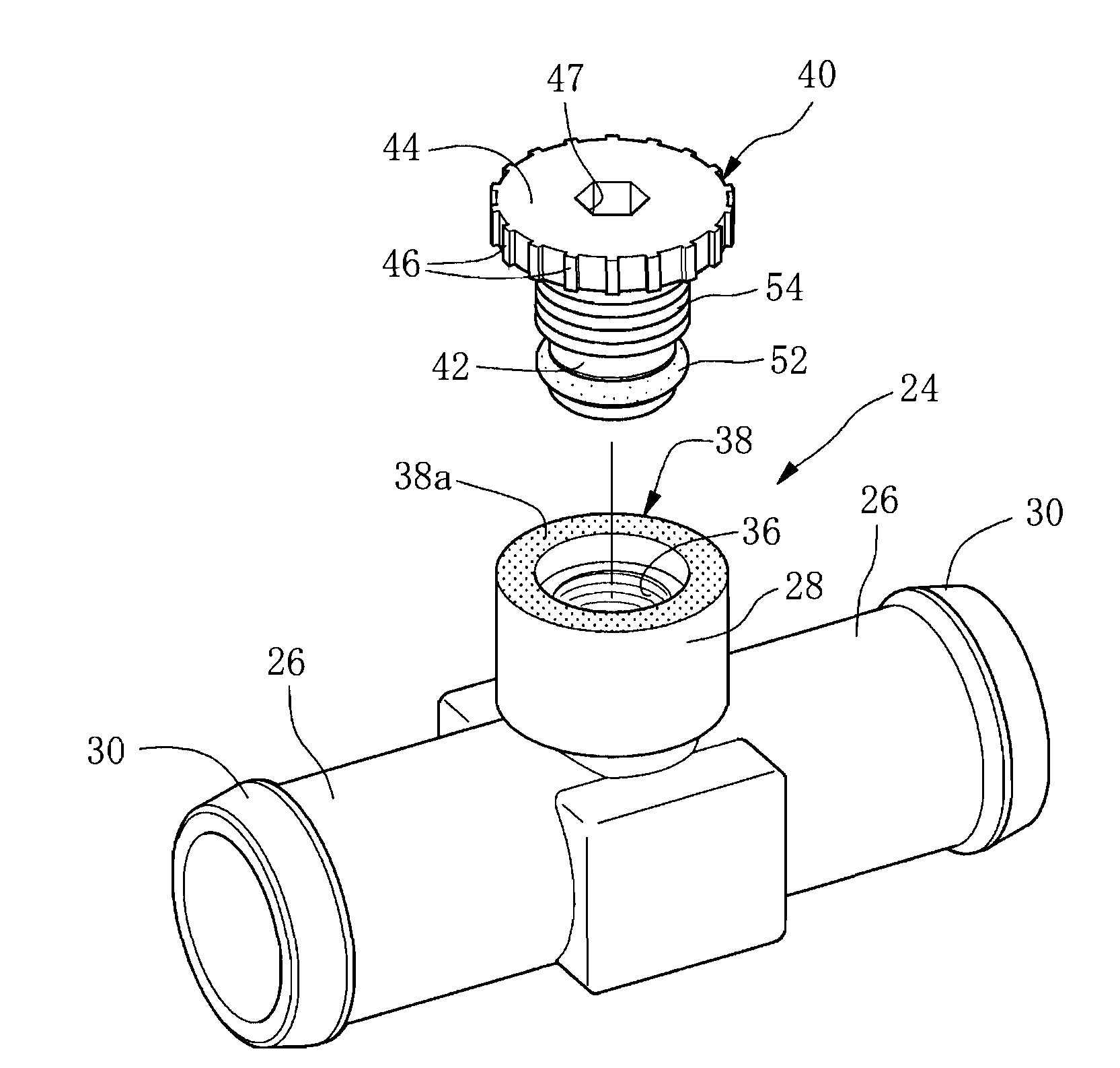
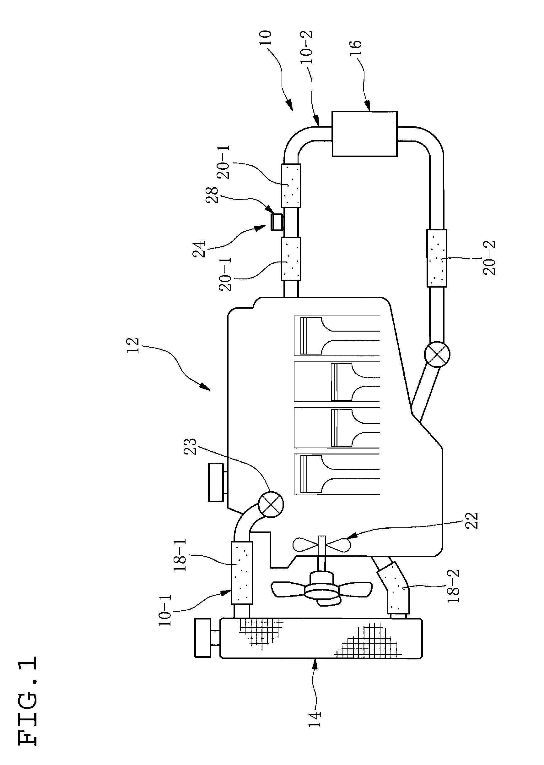
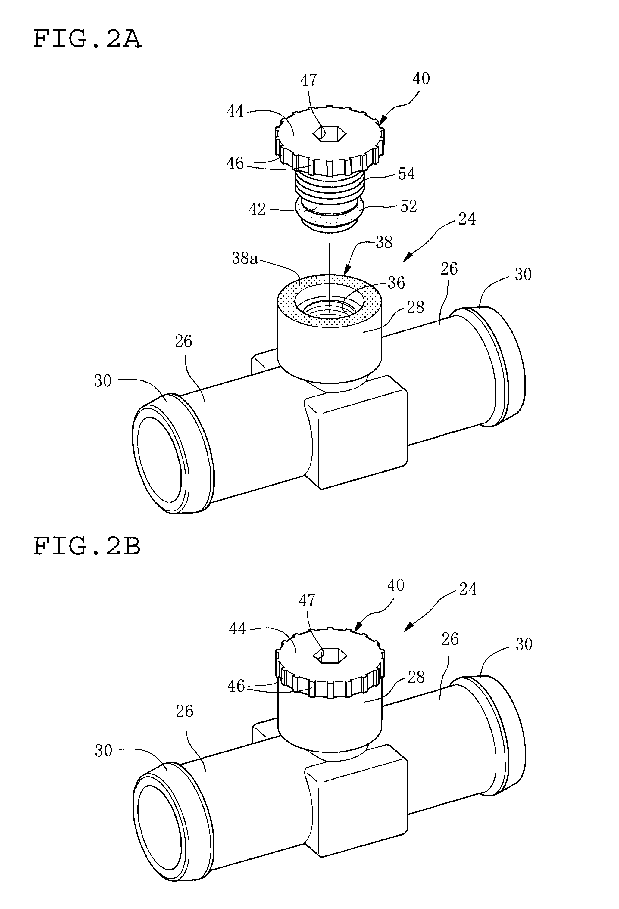
[0071]With reference to FIG. 1, reference numeral 10 indicates a circulation pipeline for an engine cooling water, reference numeral 10-1 indicates a radiator-end pipeline communicating between an engine 12 and a radiator 14, and reference numeral 10-2 indicates a heater-end pipeline communicating between the engine 12 and a heater core 16 for heating a vehicle compartment.

[0072]In the Figure, reference numeral 18-1 indicates a upper radiator hose made of rubber, constituting a part of the circulation pipeline 10, specifically a part of the radiator-end pipeline 10-1, and reference numeral 18-2 indicates a lower radiator hose.

[0073]Reference numeral 20-1 indicates an upper heater hose made of rubber, constituting similarly a part of the circulation pipeline 10, specifically a part of the heater-end pipeline 10-2, and reference numeral 20-2 indicates a lower heater hose.

[0074]Further, reference numeral 22 indicates a water pump, and reference numeral 23 indicates a thermo valve with ...


PUM


Abstract

An air bleeding pipe joint has a pair of connection pipe portions, a branch pipe portion having an air bleeding hole in an inside thereof, a plug body, and an elastic annular sealing member providing an air-tight seal between a female fitting surface of the branch pipe portion and a male fitting surface of the plug body. The plug body is removably mounted to the branch pipe portion in threaded engagement therewith such that a seating surface of the plug body seats on a seated surface of the branch pipe portion. An air discharge path is provided on an upper end of the branch pipe portion and/or the plug body with respect to a sealing position at which the sealing member is disposed for discharging outwardly an air that leaks upwardly through the sealing position.

Description

BACKGROUND OF THE INVENTION[0001]1. Field of the Invention[0002]The present invention relates to an air bleeding pipe joint connected to a circulation pipeline for an engine cooling water and adapted for bleeding an air in the circulation pipeline.[0003]2. Description of Related Art[0004]In a motor vehicle, when an engine cooling water is supplied in a circulation pipeline for the engine cooling water, an air is sometimes confined within the circulation pipeline, and as a result, it is hard to inject the engine cooling water in a radiator. As a countermeasure, an air bleeding portion has been conventionally provided at a part of the circulation pipeline.[0005]For example, Patent document 1 as below discloses a technique of providing such air bleeding portion.[0006]Further, Patent Document 2 as below also discloses such air bleeding portion provided in a circulation pipeline for an engine cooling water. According to the disclosure of Patent Document 2, an air bleeding pipe joint as t...

Claims


Application Information

Patent Timeline
IPC IPC(8): F24D19/08
CPCF01P11/028F16L55/07F16L55/1108Y10T137/3084
Inventor KATO, KAZUHIROTAKAHASHI, AKIHIKOISAJI, MASAHISA
Owner SUMITOMO RIKO CO LTD
Why Eureka
Try Eureka