Co-casting of metals by direct chill casting

a technology of metal layers and casting, applied in the field of casting metals, can solve the problems of affecting etc., and achieve the effect of reducing the production cost, and improving the quality of metals

Inactive Publication Date: 2008-08-28
NOVELIS INC
View PDF25 Cites 11 Cited by
  • Summary
  • Abstract
  • Description
  • Claims
  • Application Information

AI Technical Summary

Benefits of technology

[0011]Yet another exemplary embodiment provides an apparatus for casting a composite metal ingot, comprising: an open-ended generally rectangular mold cavity having an entry end portion, a discharge end opening, and a movable bottom block adapted to fit within the discharge end and to move axially of the mold during casting, said mold cavity having opposed side walls and opposed end walls adapted to cast a rectangular composite ingot having opposed faces and opposed ends; a divider positioned in said mold cavity and extending across the cavity towards opposite end walls thereof, thereby dividing at least the entry end portion of the mold cavity into first and second feed chambers; a first molten metal feed arrangement for feeding molten metal for a first layer of said composite ingot to one of said feed chambers; a second molten metal feed arrangement for feeding molten metal for a second layer of said composite ingot to said second feed chamber, and a guide for said divider, said guide being movable, thereby allowing said divider to be moved at times during casting relative to said mold cavity in directions towards or away from one of said side walls of the mold cavity.

Problems solved by technology

Ingots produced by both of these co-casting techniques, i.e. the use of a continuously supplied divider member that becomes incorporated into the ingot, and the provision of a cooled divider wall, may suffer from certain disadvantages, especially when intended for subsequent rolling into sheet products, such as brazing strip.
One problem is that a relatively thin coating layer formed on a thicker core ingot may be “wiped off” during rolling at the leading and trailing ends of the ingot (i.e. at the ingot head and butt ends), and also at the width sides of the ingot.
Another problem is that, because the ingot is subjected to different cooling dynamics during the main stage of the casting operation than at the start and end of casting, so that the cooling ingot is subjected to different rates of contraction in these stages, the interface between the layers may become non-planar in the final cast ingot.
This may cause differences of thickness of the coating layer after rolling.

Method used


Image

  • Co-casting of metals by direct chill casting
  • Co-casting of metals by direct chill casting
  • Co-casting of metals by direct chill casting

Examples


Embodiment Construction

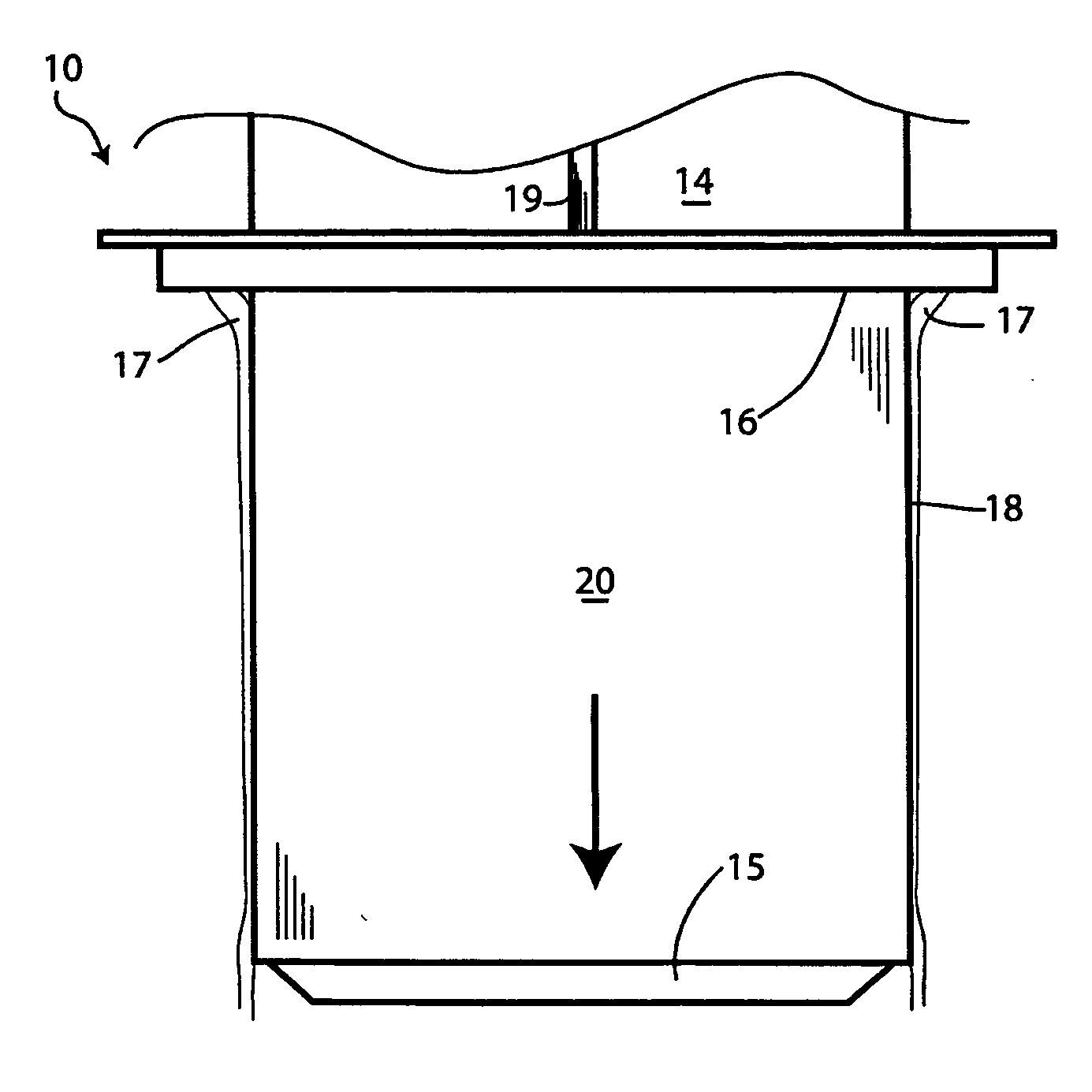
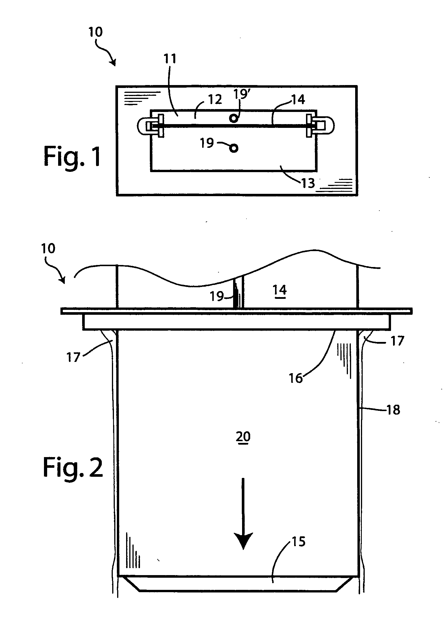
[0028]FIGS. 1 and 2 of the accompanying drawings show a modification of the Kilmer et al. casting apparatus referred to above. It will of course be realized by persons skilled in the art that FIGS. 1 and 2 are greatly simplified and that a working version of the apparatus will require additional equipment and structures, all of which will be apparent to a skilled artisan.

[0029]FIGS. 1 and 2 show a rectangular direct-chill casting mold 10 having a mold cavity 11 which is divided into two mold chambers (i.e. metal feed chambers) 12 and 13 by a vertical divider member 14. The divider member 14 may be attached to a bottom block 15, which is positioned at a discharge end opening (i.e. an outlet) 16 of the mold cavity during start-up and is fed into the mold from above by a supporting and feed apparatus (not shown). The divider member 14 may be made of a suitable metal, e.g. aluminum, an aluminum alloy, or a clad aluminum product that preferably has a solidus temperature greater than the ...


PUM

PropertyMeasurementUnit
temperatureaaaaaaaaaa
angleaaaaaaaaaa
angleaaaaaaaaaa

Abstract

Apparatus and method of co-casting metal ingots in direct-chill casting apparatus. The apparatus and method employs at least one divider (divider member or divider wall) that separates a casting mold into two or more chambers for receiving molten metal that is combined into a single ingot. The divider may be moved, angled and / or flexed during casting to produce ingots that are designed primarily for rolling into thin plate or sheet. The ingot has at least one outer layer that is thicker adjacent to the side (width) edges than in the center, and / or thicker adjacent to the butt or head regions. This compensates for wiping of the outer layer from the ingot core during rolling. Also, the divider may be outwardly bowed outwardly towards one of the mold walls during the casting run.

Description

CROSS-REFERENCE TO RELATED APPLICATIONS[0001]This invention claims the priority right of patent application Ser. No. 60 / 904,212 filed on Feb. 28, 2007 by applicants herein.BACKGROUND OF THE INVENTION[0002](1) Field of the Invention[0003]This invention relates to the casting of metals, particularly aluminum and aluminum alloys, by direct chill casting techniques. More particularly, the invention relates to the co-casting of metal layers by direct chill casting.[0004](2) Description of the Related Art[0005]Metal ingots are commonly produced by direct chill (DC) casting of molten metals in which a molten metal is poured into a mold having an open upper end and (after start-up) an open lower end. The metal emerges from the lower end of the mold as a metal ingot that descends as the casting operation proceeds. In other cases, the casting takes place horizontally, but the procedure is essentially the same. Such casting techniques are particularly suited for the casting of aluminum and alu...

Claims


Application Information

Patent Timeline
Patent Type & Authority Applications(United States)
IPC IPC(8): B22D11/049B22D15/04
CPCB22D11/049B22D11/007
Inventor WAGSTAFF, ROBERT BRUCE
Owner NOVELIS INC
Why Eureka
Try Eureka