Voltage regulator with leakage current compensation

a voltage regulator and compensation technology, applied in the direction of electrical variable regulation, process and machine control, instruments, etc., can solve the problems of large leakage current flow through the regulation transistor, inability to adjust the output voltage of the ldo regulator as desired, and more significant problems

Inactive Publication Date: 2008-08-28
STMICROELECTRONICS SRL
View PDF19 Cites 29 Cited by
  • Summary
  • Abstract
  • Description
  • Claims
  • Application Information

AI Technical Summary

Benefits of technology

[0019]An aspect of the present invention is a voltage regulator having an input terminal for receiving an input voltage and an output terminal for providing a regulated voltage, the voltage regulator including: a differential amplifier configured for receiving a reference voltage, and a feedback signal being a function of the regulated voltage, and for providing a regulation signal according to a comparison between the reference voltage and the feedback signal, a regulation transistor having a control terminal for receiving the regulation

Problems solved by technology

A drawback of known LDO regulators is that a relatively large leakage current flows through the regulation transistor even when it is biased for being off.
Such leakage current gives a non-negligible contribution to the quiescent current (especially when no load is connected to the voltage regulator), so that the output voltage of the LDO regulator is not adjustable as desired.
Moreover, such a problem is more significant as t

Method used


Image

  • Voltage regulator with leakage current compensation
  • Voltage regulator with leakage current compensation
  • Voltage regulator with leakage current compensation

Examples


Embodiment Construction

[0026]In the following description, similar elements are denoted by same references.

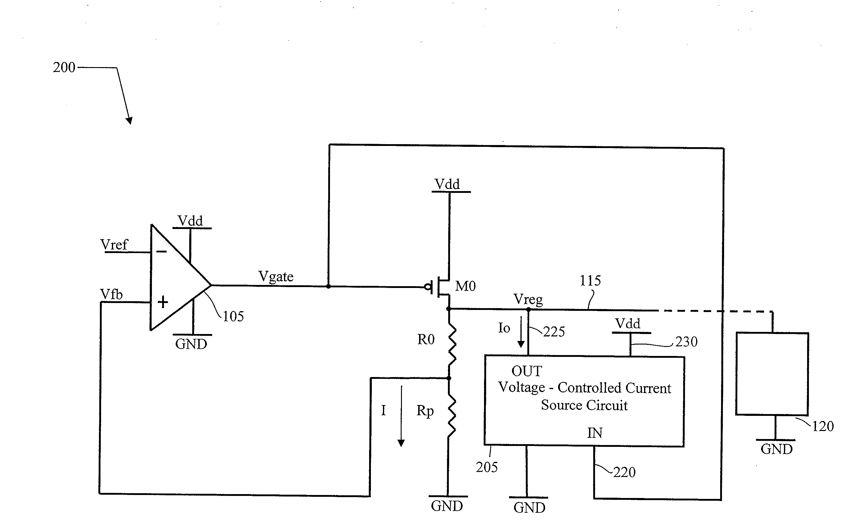
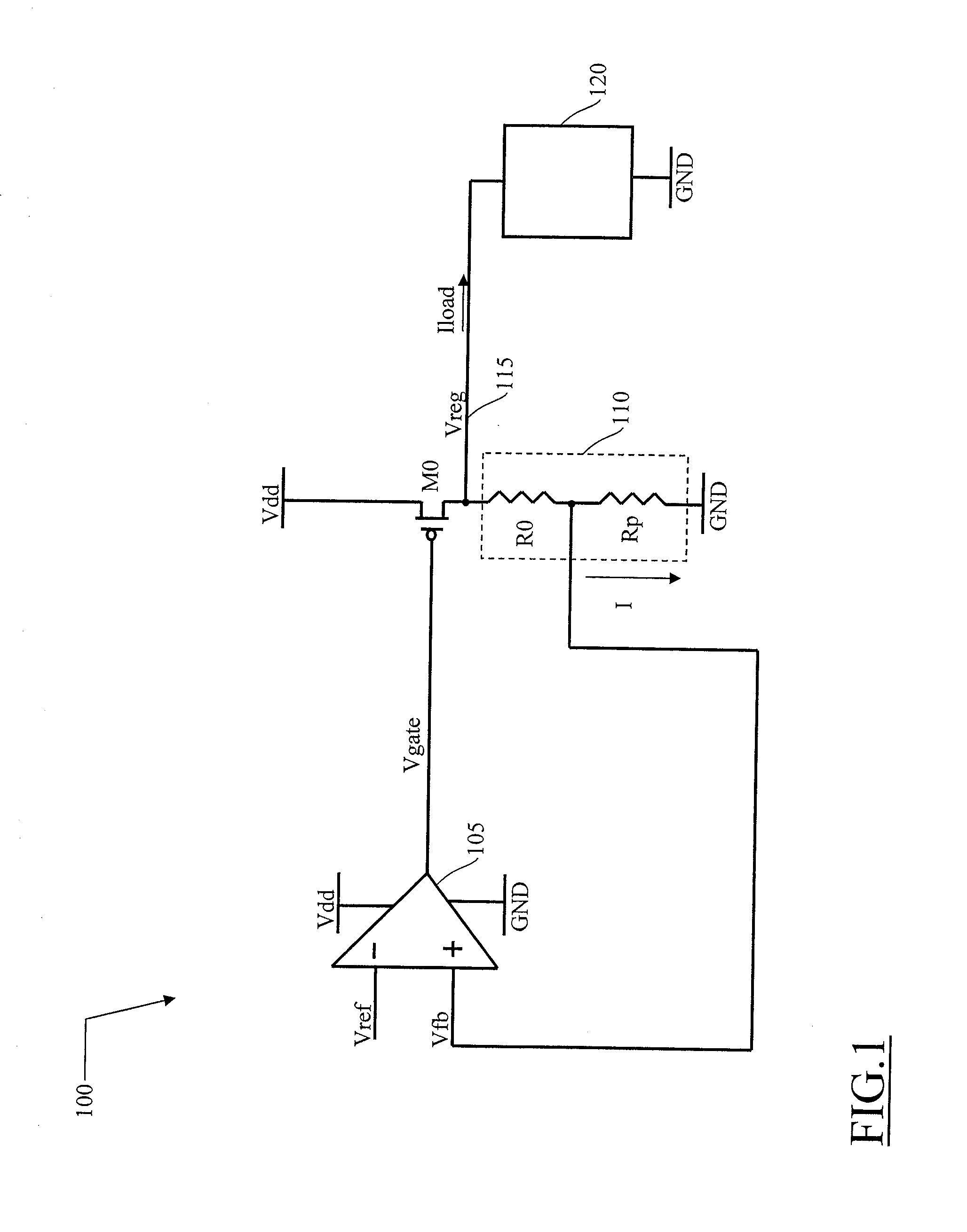
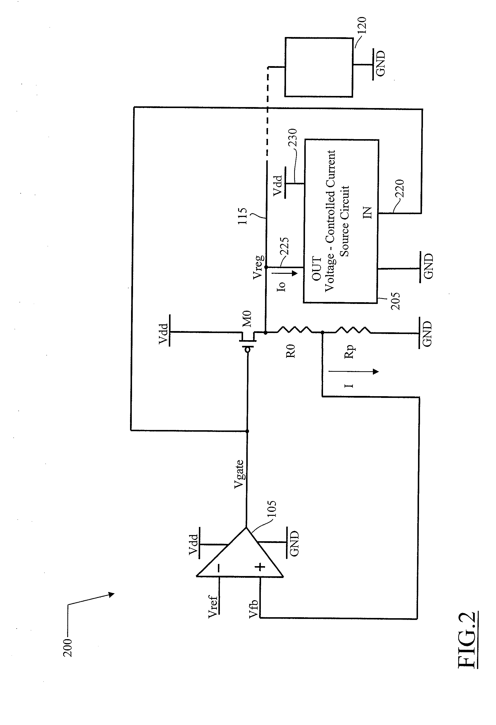
[0027]Referring to FIG. 1, a conventional implementation of a voltage regulator 100 is schematically depicted. The voltage regulator 100 includes a differential amplifier 105, which receives as supply a ground voltage GND and a supply voltage Vdd (such as, 3V). The differential amplifier 105 has an inverting input terminal (labeled “−” in the drawing) that receives a comparison reference voltage Vref (such as, 1V), and a non-inverting input terminal (labeled “+” in the drawing) that receives a feedback signal Vfb (as described in the following). An output terminal of the differential amplifier 105 generates a regulation signal Vgate, which is applied to a control terminal of a regulation p-channel MOS transistor M0. The transistor M0 has a source terminal that receives the supply voltage Vdd, and a drain terminal that is connected to a voltage divider 110. The voltage divider 110 includes a first res...


PUM


Abstract

A voltage regulator having an input terminal for receiving an input voltage and an output terminal for providing a regulated voltage, the voltage regulator including: a differential amplifier configured for receiving a reference voltage and a feedback signal being a function of the regulated voltage, and for providing a regulation signal according to a comparison between the reference voltage and the feedback signal, a regulation transistor having a control terminal for receiving the regulation signal, a first terminal for receiving the first voltage and a second terminal coupled with the output terminal of the voltage regulator, wherein a voltage-controlled circuit coupled to the output terminal, responsive to a voltage difference between the first voltage and the regulation voltage and adapted to sink from the output terminal a current depending on said voltage difference between the supply voltage and the regulation voltage, said current being related to a leakage current of the regulation transistor.

Description

BACKGROUND OF THE INVENTION[0001]1. Field of the Invention[0002]The present invention relates to the field of semiconductor Integrated Circuits (ICs); more particularly, the invention relates to voltage regulators integrated in chips of semiconductor material.[0003]2. Discussion of the Related Art[0004]Voltage regulators are regulator circuits which are able to provide a target, constant voltage to the integrated circuits which are coupled thereto.[0005]Typically, the voltage regulators are used for performing a conversion from an input voltage to an operative voltage required by the integrated circuit (which may be for example a full-custom integrated circuit, an Application Specific Integrated Circuit—ASIC—, a Programmable Logic Device—PLD) for the correct operation thereof. In particular, the voltage regulators are able to modulate the voltage that is output, so as to make different values of the operative voltages available.[0006]With the trend in integrated circuit fabrication ...

Claims


Application Information

Patent Timeline
IPC IPC(8): G05F1/563
CPCG05F1/565
Inventor LO LACONO, GIOACCHINOMILAZZO, PATRIZIATRICOMI, SALVATORE
Owner STMICROELECTRONICS SRL
Why Eureka
Try Eureka