LED chain failure detection

a technology of led chain and failure detection, applied in the direction of electric variable regulation, process and machine control, instruments, etc., can solve the problems of affecting the overall system efficiency, affecting the relative power savings of a cluster with a minimal amount of leds, and affecting the current of a large amoun

Inactive Publication Date: 2008-08-28
GE LIGHTING SOLUTIONS LLC
View PDF7 Cites 51 Cited by
  • Summary
  • Abstract
  • Description
  • Claims
  • Application Information

AI Technical Summary

Benefits of technology

[0007]Accordingly, there is a need for more non-invasive systems and methods to detect single LED failure within an LED cluster.
[0008]In accordance with one aspect of the present exemplary embodiment, a system detects failure within an LED array that includes a first section with a plurality of LEDs. One or more sections, that include a plurality of LEDs, are coupled to each other and to the first section. A non-invasive monitoring circuit is coupled remotely to each of the sections to monitor at least one of a power, a current and a voltage parameter for each of the sections. A control circuit triggers an output if one or more of the parameters for any one section are greater than a predetermined threshold for the relative parameter value for any other section.

Problems solved by technology

Because the voltage versus current characteristics of the LED are much like any diode (that is, current approximately an exponential function of voltage), a small voltage change results in a huge change in current.
Added to deviations in the process, this means that a voltage source may barely make one LED light while taking another of the same type beyond its maximum ratings and potentially destroying it.
However, such a solution can affect overall system efficiency due to significant power dissipation caused by using such sense resistors.
In such applications, the relative power savings of a cluster with a minimal amount of LEDs can be greatly affected by the use of large current consumption devices such as inline sense resistors.
The resulting increase in pin count can preclude the use of smaller, more desirable chip packaging for conventional power circuits.

Method used


Image

  • LED chain failure detection
  • LED chain failure detection
  • LED chain failure detection

Examples


Embodiment Construction

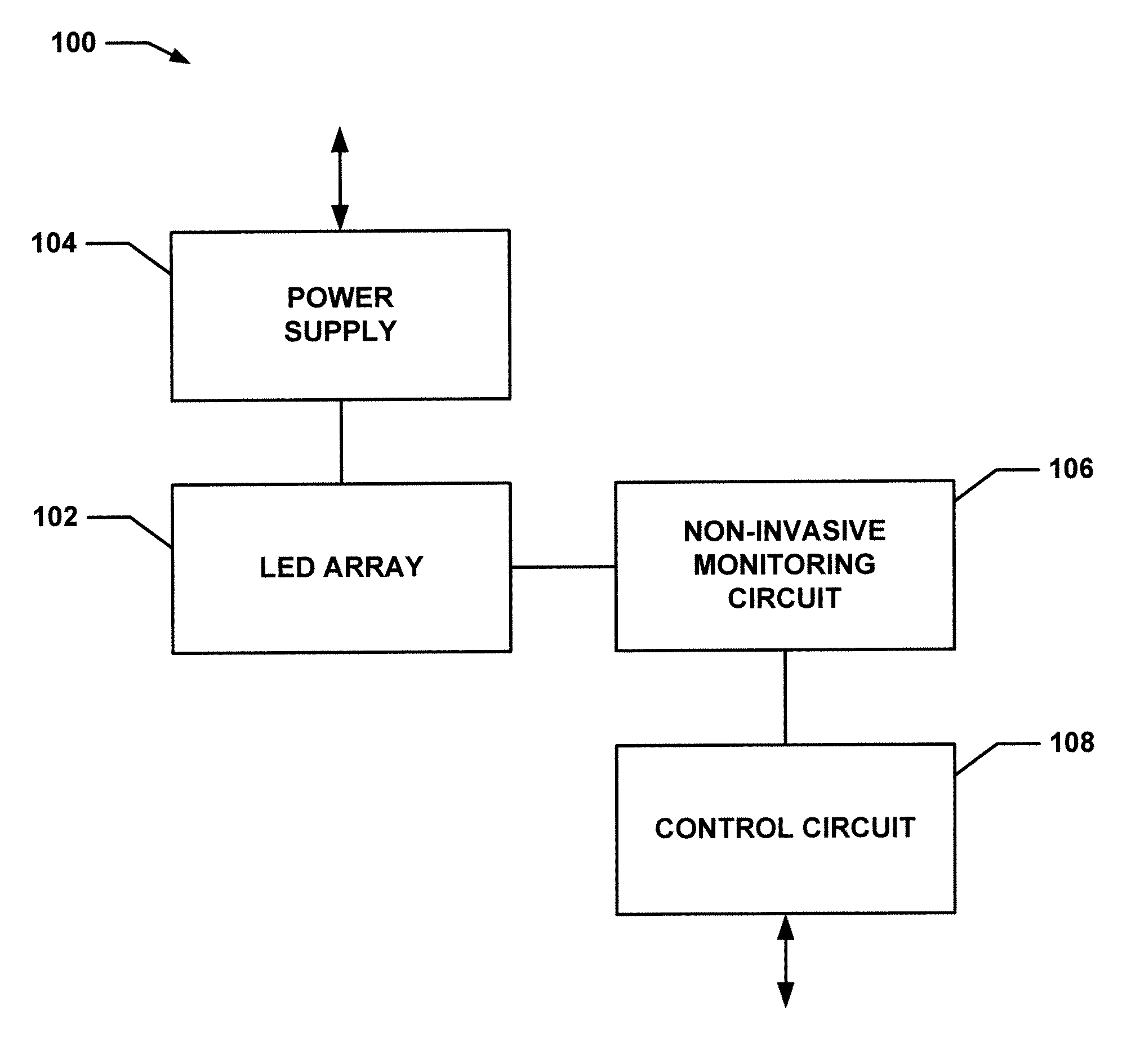
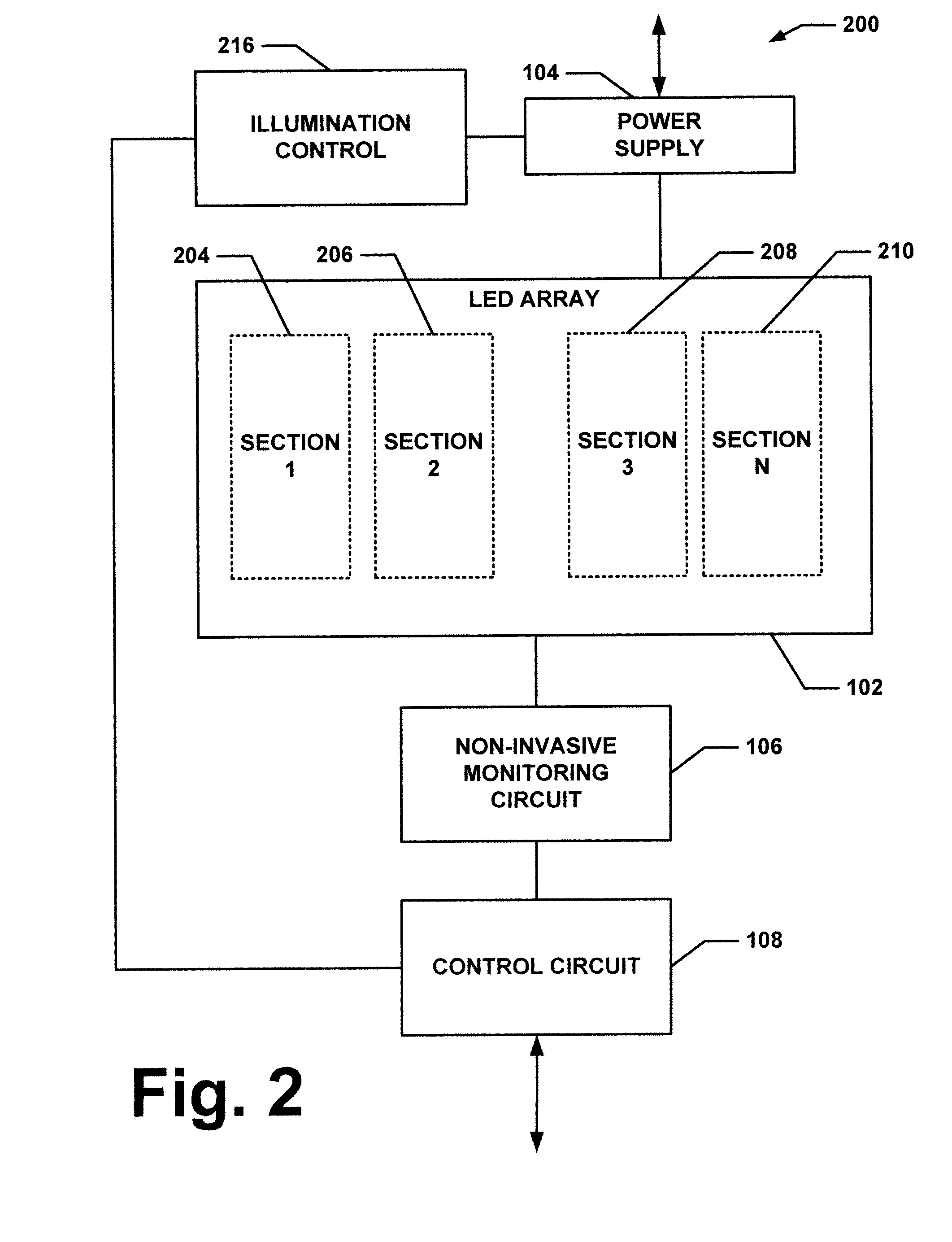
[0013]FIG. 1 illustrates a lighting system 100 that includes an LED array 102 that is energized via a power supply 104. The LED array 102 interfaces with a non-invasive monitoring circuit (NIMC) 106 that monitors one or more aspects of the LED array (e.g., light output, current draw, etc.). A control circuit 108 is coupled to the NIMC 106 to compare values read by the NIMC 106 to one or more predetermined parameters. If the values from the NIMC 106 are outside such predetermined thresholds, the control circuit 108 can provide an output (e.g., to a disparate system, to maintenance personnel, etc.) to provide such indication.

[0014]The LED array 102 can include a number of disparate configurations. In one example, the LED array 102 includes a plurality of LEDs connected in series. Power is delivered across the serially connected LEDs via the power supply 104. In a second example, the LED array 102 includes a plurality of serially connected LEDs wherein each serial connection is coupled...


PUM


Abstract

The system consists of an LED failure detection circuit to provide protection against individual LED catastrophic failure. When LED clusters are arranged in a series-parallel configuration, it is important to detect individual LED failure in order to avoid uncontrolled luminous intensity reduction and/or light uniformity degradation. The circuit compares the voltage levels on LEDs with similar position but situated in different chains. In normal conditions, the voltage levels are substantially similar to one another. In case of individual or multiple LED failure, open or shortcircuit, the circuit sends a signal to the automatic turn off circuit that initiates the lamp forced turn off sequence.

Description

BACKGROUND[0001]The present exemplary embodiment relates to light emitting diodes (LEDs). It finds particular application in conjunction with control of the intensity and uniformity of LEDs by indentifying failure conditions, and will be described with particular reference thereto. However, it is to be appreciated that the present exemplary embodiment is also amenable to other like applications.[0002]In many lighting applications, LEDs are selected to provide illumination instead of an incandescent or other conventional illumination sources. Generally, the LEDs are arranged in clusters or arrays to coincide with particular design specifications to provide a desired light output. Because the voltage versus current characteristics of the LED are much like any diode (that is, current approximately an exponential function of voltage), a small voltage change results in a huge change in current. Added to deviations in the process, this means that a voltage source may barely make one LED l...

Claims


Application Information

Patent Timeline
Patent Type & Authority Applications(United States)
IPC IPC(8): G01R31/00H05B37/02H05B44/00
CPCY02B20/341H05B33/089H05B45/50Y02B20/30
Inventor MIHAI, DANAMMARI, MOHAMMED
Owner GE LIGHTING SOLUTIONS LLC
Why Eureka
Try Eureka