
Integrated Eas/Rfid Device and Disabling Devices Therefor

a technology of eas and rfid, which is applied in the field of integrated electronic article surveillance (eas) and radiofrequency identification (rfid) devices, can solve the problems of inability to reactivate, short circuit, and previously known combination eas and rfid devices or tags or labels

Inactive Publication Date: 2008-08-28
TYCO FIRE & SECURITY GMBH
View PDF16 Cites 23 Cited by
  • Summary
  • Abstract
  • Description
  • Claims
  • Application Information

AI Technical Summary

Benefits of technology

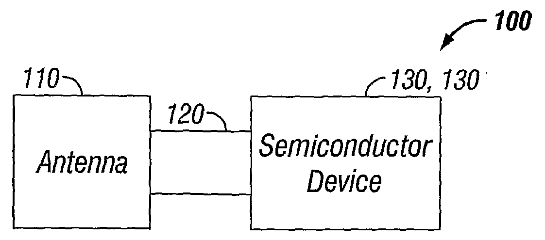
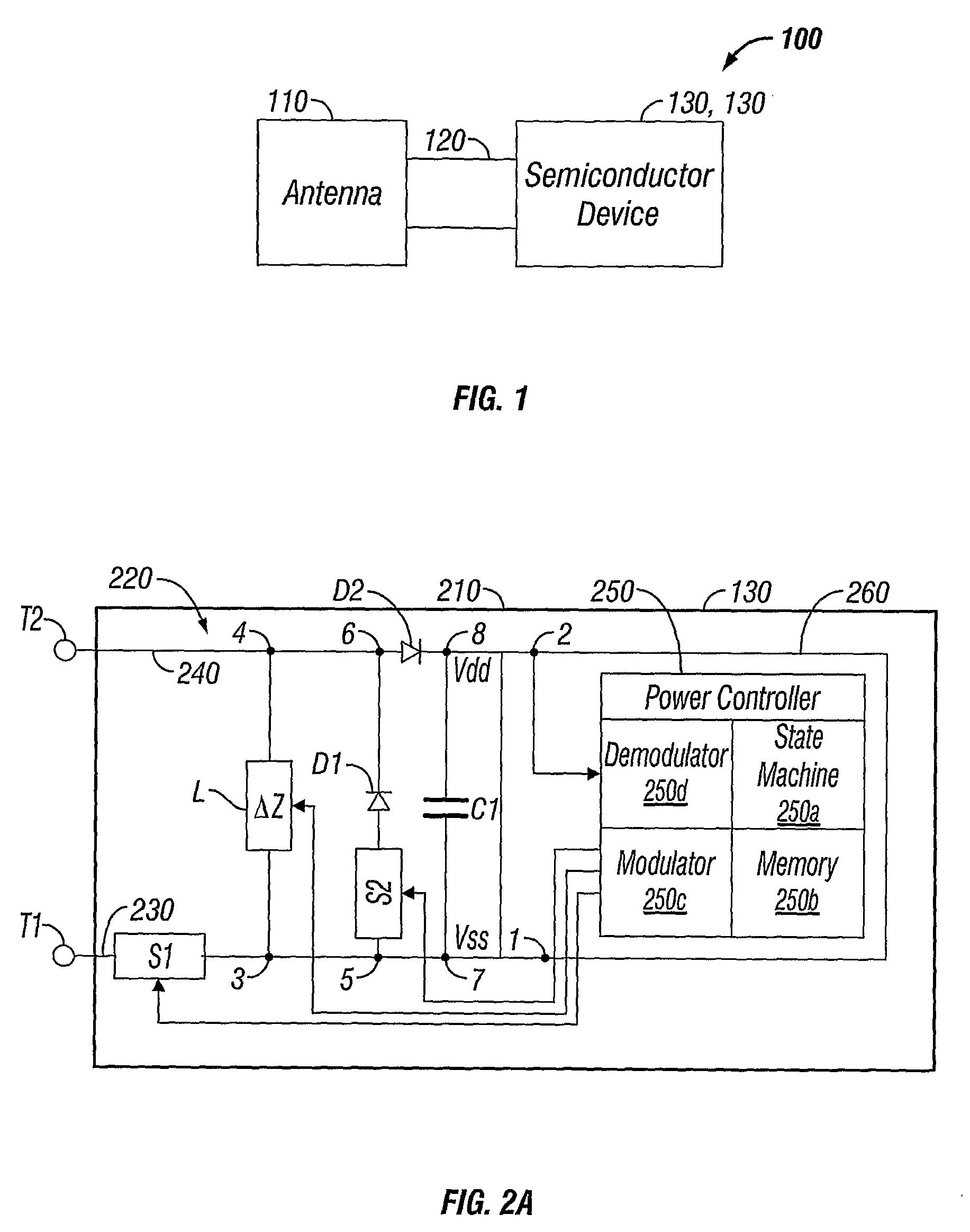
[0003]This invention relates to an integrated electronic article surveillance (EAS) and radiofrequency identification (RFID) device which is capable of performing dual EAS / RFID functions and particularly to a device which is capable of being reactivated to resume performance of both EAS and RFID functions.

Problems solved by technology

However, in the case of EAS markers which are deactivated by means of a radiofrequency wave typically at a range of about 8.2 MHz (±10%), such as an RF LC (radiofrequency inductor capacitor) resonant marker, an induced high voltage can break down the dielectric layer at a weak spot, creating a short circuit.
This is a destructive process and, typically, reactivation is not possible.
However, there are several issues pertaining to previously known combination EAS and RFID devices or tags or labels.
Cost—Combined EAS / RFID tags or labels are generally more expensive for a retailer / manufacturer since two devices and two separate readers or deactivators are typically required.
Interference—Interference can occur, if the devices are overlapped resulting in degrading performance of either or both EAS and RFID functions, unless specific design features are provided to reduce the interference caused by the overlapping.
However, with respect to integrated EAS / RFID markers, there is no known solution to the problem of reactivating the EAS function of the EAS / RFID marker after deactivation.

Method used


Image

  • Integrated Eas/Rfid Device and Disabling Devices Therefor
  • Integrated Eas/Rfid Device and Disabling Devices Therefor
  • Integrated Eas/Rfid Device and Disabling Devices Therefor

Examples


Embodiment Construction

[0020]An integrated EAS / RFID device typically does not provide complete functionality without an appropriate method of deactivation especially with respect to the EAS function of the device. (An EAS marker or label is commonly referred to as a single bit transponder because it contains only one piece of information: whether the label is activated or de-activated.) The integrated EAS / RFID device of the present disclosure is capable of performing dual EAS / RFID functions, i.e., the RFID function provides extensive information about the tagged item while the attached EAS function provides limited information regarding the item (activated / de-activated).

[0021]In general, the detection range of the EAS function is greater than the detection range of the RFID function. One attractive feature of such an integrated device is that it is possible to provide an EAS deactivation function based on complicated code preset in the RFID device. Once confirmed, the RFID portion of the integrated device...


PUM


Abstract

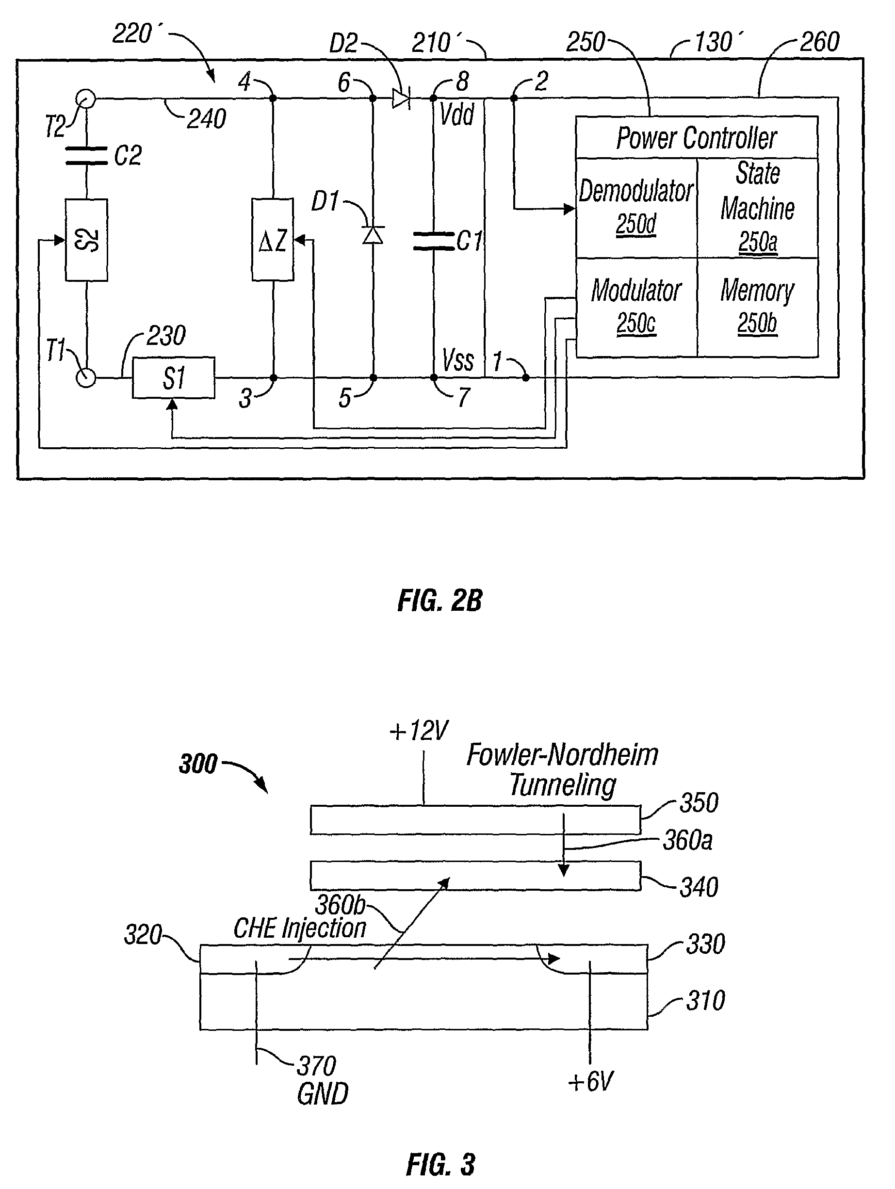
An integrated electronic article surveillance (EAS) and radiofrequency identification (RFID) marker is provided which a semiconductor device which may he coupled to an antenna for receiving and retransmitting energy and signals to the antenna. A current receiving front end section of the semiconductor device communicates with at least one other section of the device so more than one function can be implemented upon receiving and retransmitting energy and signals. A first switch is operatively coupled to the front end section such that the functions are entirely but reversibly disabled upon closure of the first switch thereby effecting a reversible EAS function. A second switch is operatively coupled to the front end section such that at least one of the functions is at least partially disabled upon closure of the second switch. RFID functions of the marker am retained upon EAS deactivation.

Description

CROSS-REFERENCE TO RELATED APPLICATIONS[0001]This application claims the benefit of priority under 35 U.S.C. §119 of U.S. Provisional Patent Application Ser. No. 60 / 630,3 51 filed on Nov. 23, 2004 entitled “Disabling Devices for an Integrated EAS / RFID Device”, the entire contents of which is incorporated by reference herein.BACKGROUND OF THE INVENTION[0002]1. Technical Field[0003]This invention relates to an integrated electronic article surveillance (EAS) and radiofrequency identification (RFID) device which is capable of performing dual EAS / RFID functions and particularly to a device which is capable of being reactivated to resume performance of both EAS and RFID functions.[0004]2. Background of Related Art[0005]In general, it is known that many devices which are designed to perform only an EAS function (i.e., marking an article as “activated” or “deactivated”) are capable of being reactivated. For example, magnetic processes for deactivating an EAS marker provide a simple process...

Claims


Application Information

Patent Timeline
IPC IPC(8): G08B13/14
CPCG06K7/0008G06K19/0723G08B13/2448G08B13/2417G06K19/07749G06K19/07G06K19/00
Inventor LIAN, MING-RENSHAFER, GARY MARK
Owner TYCO FIRE & SECURITY GMBH
Learn More