Apparatus And Method Of Using A Led Light Source To Generate An Efficent, Narrow, High-Aspect Ratio Light Pattern

a technology of led light source and light pattern, which is applied in the field of apparatus and method of using led light source to generate an efficent, narrow, high-aspect ratio light pattern, can solve the problems of high investment cost, ccfl can require nearly 30 seconds of warm-up before it is stable enough to calibrate, and achieve the effect of enhancing the beam

Inactive Publication Date: 2008-08-28
ILLUMINATION MANAGEMENT SOLUTIONS
View PDF20 Cites 30 Cited by
  • Summary
  • Abstract
  • Description
  • Claims
  • Application Information

AI Technical Summary

Benefits of technology

[0017]The preferred embodiment of the invention can create a line of light that is very nearly or approximately perpendicular to its output surface at least within the range of functional equivalence to perpendicularity in the context of this disclosure. This is very beneficial to use this light in a system as additional lenses, diffusers and other optical elements can further enhance the beam for a particular application without losses associated with non-collimated illumination devices.
[0018]A plurality of light sources in a device according the illustrated embodiments of the invention allows color combining and other effects when the apparatus further comprises means for individually controlling the intensity of light from each of the light sources, such as conventional drive circuits coupled to the light sources.

Problems solved by technology

The initial investment cost of LED illumination is very expensive when compared with traditional lighting means using the cost / lumen as the metric.
While this may change over time, this high investment cost places a premium on collection and distribution efficiency of the LED optical system.
However, the CCFL can require nearly 30 seconds of warm-up before it is stable enough to calibrate for operation.
Utilizing a strip of closely spaced traditional LEDs, however, presents its own problem of thermal heat load due to the close proximity required to get a smooth light output.
This will cause the LED based system's calibration to change over time.
This is a marked disadvantage for image quality in these devices.
The multiple LEDs may change in intensity as they age, resulting in a non-uniform device.

Method used


Image

  • Apparatus And Method Of Using A Led Light Source To Generate An Efficent, Narrow, High-Aspect Ratio Light Pattern
  • Apparatus And Method Of Using A Led Light Source To Generate An Efficent, Narrow, High-Aspect Ratio Light Pattern
  • Apparatus And Method Of Using A Led Light Source To Generate An Efficent, Narrow, High-Aspect Ratio Light Pattern

Examples


Embodiment Construction

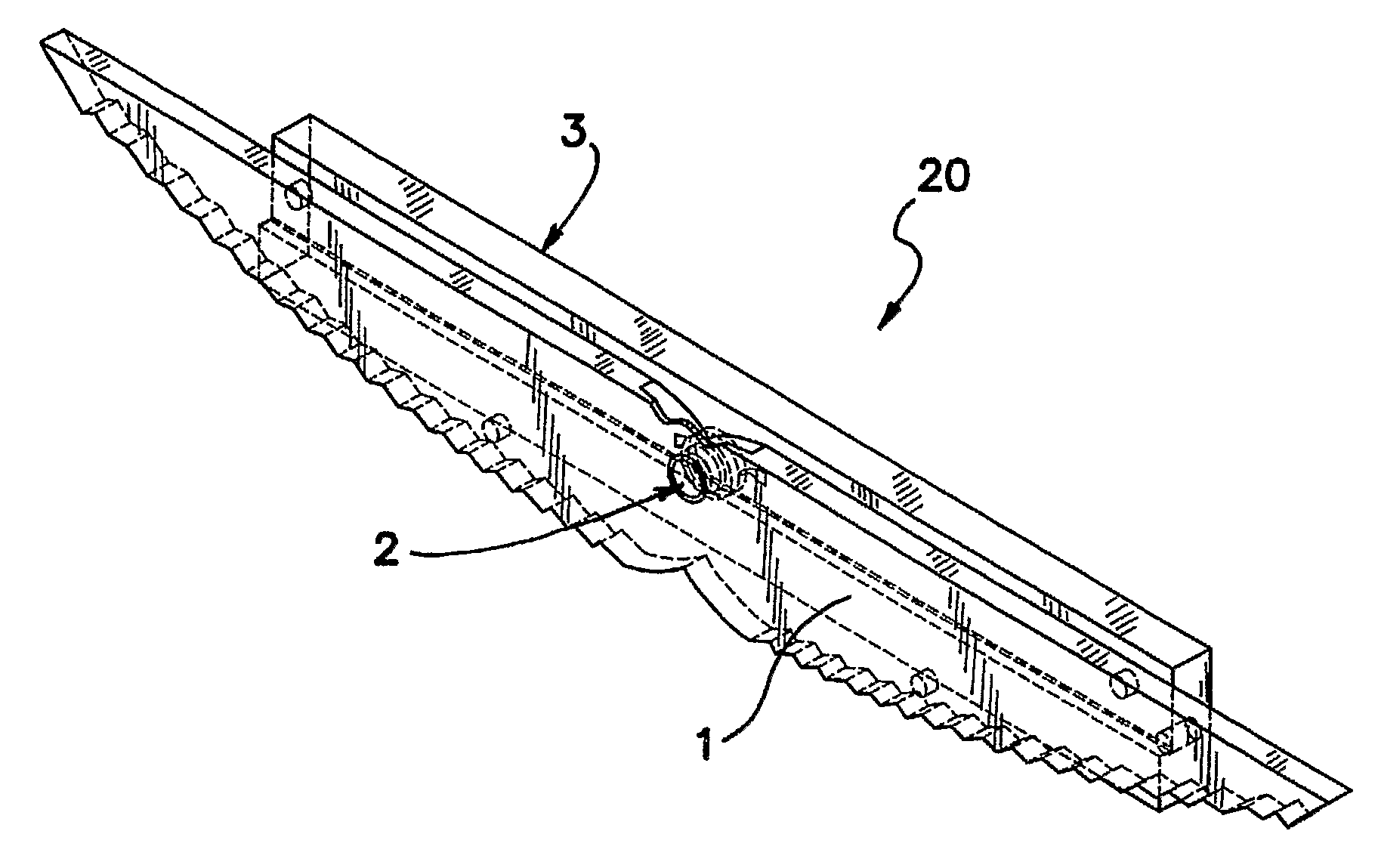
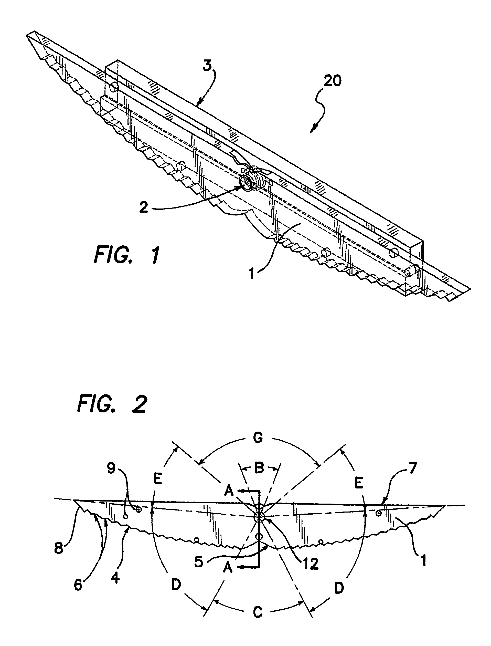
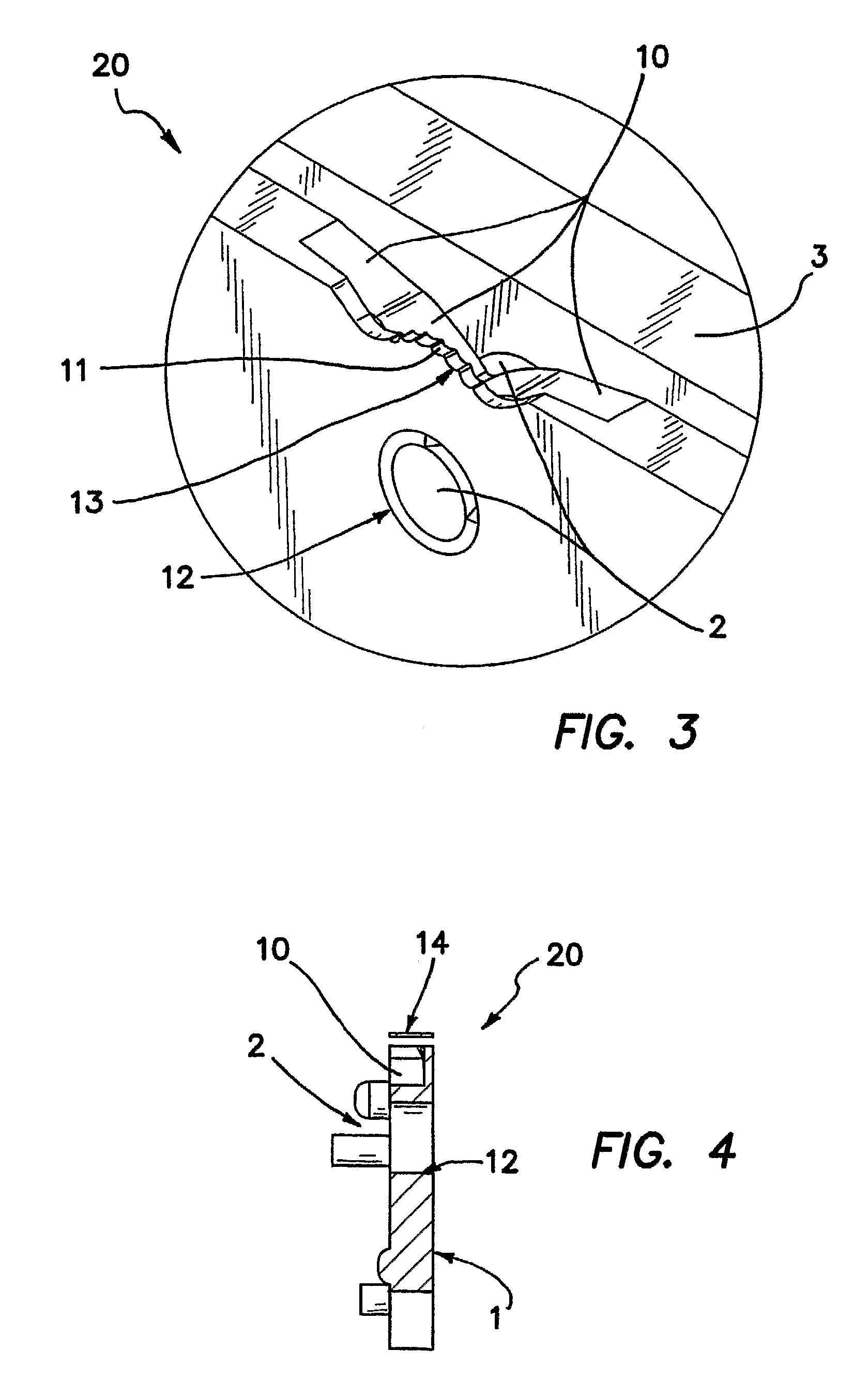
[0034]Turn to FIGS. 1-5 wherein the illustrated embodiment of the optical portion of the invention is depicted. FIG. 1 is three quarter perspective view of the device, generally denoted by reference numeral 20, which is comprised of an assembly of various optical and mechanical elements described below. One of the optical elements is a reflective cavity 1, referred to in the descriptions as the birdwing in which the side emitter LED 2 is depicted as being inserted into a nearly cylindrical aperture 12 while being attached to heat sink 3. By LED it is understood to include a solid state light emitting diode package, which includes a semiconductor substrate in which the light emitting junction is defined, electrical leads, passivation layers and a lens or lens assembly mounted on or forming part of the passivating package around the junction and substrate. The illustrated embodiment employs an LED 2, but it is to be understood that any light source may be employed which is now known o...


PUM


Abstract

An LED light source produces a narrow beam of light having a linear field of illumination, which is substantially uniform across the linear field. The light source comprises at least one light emitting diode (LED) and preferably a plurality of LEDs, an optical element for the efficient collection of energy radiating from the LED or LEDs, and an optical element for distributing the collected energy into the linear field of illumination. The apparatus also includes a device or heat sink for thermal management. One or more electronic control circuits are coupled to the LED or LEDs to variably and selectively control them. When a plurality of LEDs are used, the colors produced by the LEDs may different so that the light source is collectively controllable to provide a range of optically mixed colors.

Description

RELATED APPLICATIONS[0001]The present application is related to U.S. Provisional Patent Application Ser. No. 60 / 676,590, filed on Apr. 28, 2005, which is incorporated herein by reference and to which priority is claimed pursuant to 35 USC 119.BACKGROUND OF THE INVENTION[0002]1. Field of the Invention[0003]The invention relates to the field of apparatus and method for using light emitting diodes (LED) or other light sources to generate an efficient, narrow, high-aspect ratio beam.[0004]2. Description of the Prior Art[0005]The initial investment cost of LED illumination is very expensive when compared with traditional lighting means using the cost / lumen as the metric. While this may change over time, this high investment cost places a premium on collection and distribution efficiency of the LED optical system. The more efficient the system, the better the cost / benefit comparison with traditional illumination means, such as incandescent, fluorescent and neon.[0006]A useful illumination...

Claims


Application Information

Patent Timeline
Patent Type & Authority Applications(United States)
IPC IPC(8): F21S13/00
CPCB60Q1/2611H04N1/02885B60Q1/54F21S48/215F21S48/218F21S48/2243F21S48/2262F21S48/2287F21S48/23F21S48/328F21V29/004F21Y2101/02G02B6/0018G02B6/0021G02B6/0038G02B6/0046H04N1/00989H04N1/02815H04N1/02835B60Q1/302F21V29/70F21Y2115/10F21S43/14F21S43/15F21S43/239F21S43/243F21S43/247F21S43/30F21S45/48
Inventor HOLDER, RONALD G.RHOADS, GREG
Owner ILLUMINATION MANAGEMENT SOLUTIONS
Why Eureka
Try Eureka