
Mobile Communication Device

a communication device and mobile technology, applied in the direction of transmission, substation equipment, near-field systems using receivers, etc., can solve the problems of increasing problems, insufficient reception and transmission of electromagnetic signals, and ignoring complete interference or nullities of electromagnetic fields

Inactive Publication Date: 2008-08-28
NXP BV
View PDF11 Cites 22 Cited by
  • Summary
  • Abstract
  • Description
  • Claims
  • Application Information

AI Technical Summary

Benefits of technology

[0008]The characteristic features according to the invention provide the advantage that the shielding or attenuating of electromagnetic fields between the first and the second area by electromagnetically shielding components is overcome, so that wireless communication is no longer restricted to the first area. Hence, RF communication means like NFC devices can be arranged in both the first and the second area. Further, electromagnetic signals arriving in the second area are received by an antenna in the first area. Even in the case where a PCB of the communication device causes electromagnetic shielding, it is still possible to position RF communication means on both sides of a PCB of the device, since the magnetic flux of electromagnetic signals is guided between the first and the second area. Compared with prior art devices RF communication capability of electronic circuits located in the second area is dramatically increased. It should be observed that the term “shielding component” as used throughout this text is to be understood in a sense that it does not necessarily cause complete shielding of electromagnetic fields, but attenuates a magnetic field to some extent. It should further be noted that the ferrite is not necessarily arranged in the first area as a whole. The ferrite may rather be part of the second area too.
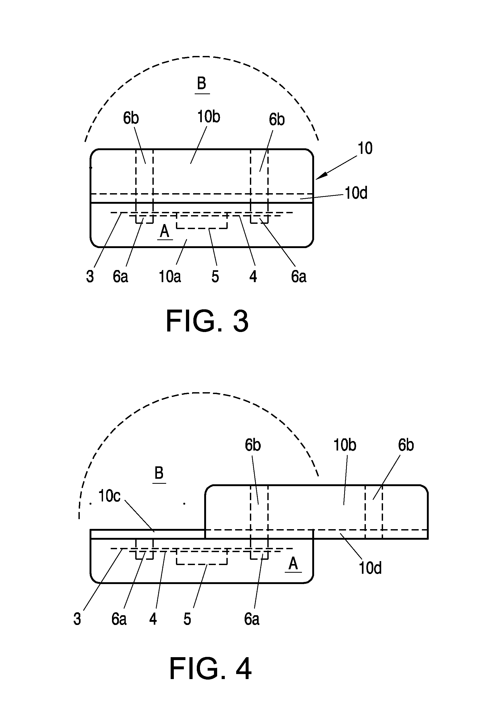
[0009]It is advantageous when said ferrite is arranged to bridge the first area with the second area and / or when said ferrite penetrates said shielding components. These measures provide the advantage that the magnetic flux is guided with high coupling efficiency between the first and second areas. For instance, when the shielding component is a multi-layer PCB comprising at least one grounding layer, a through hole can be provided in the PCB through which the ferrite projects.
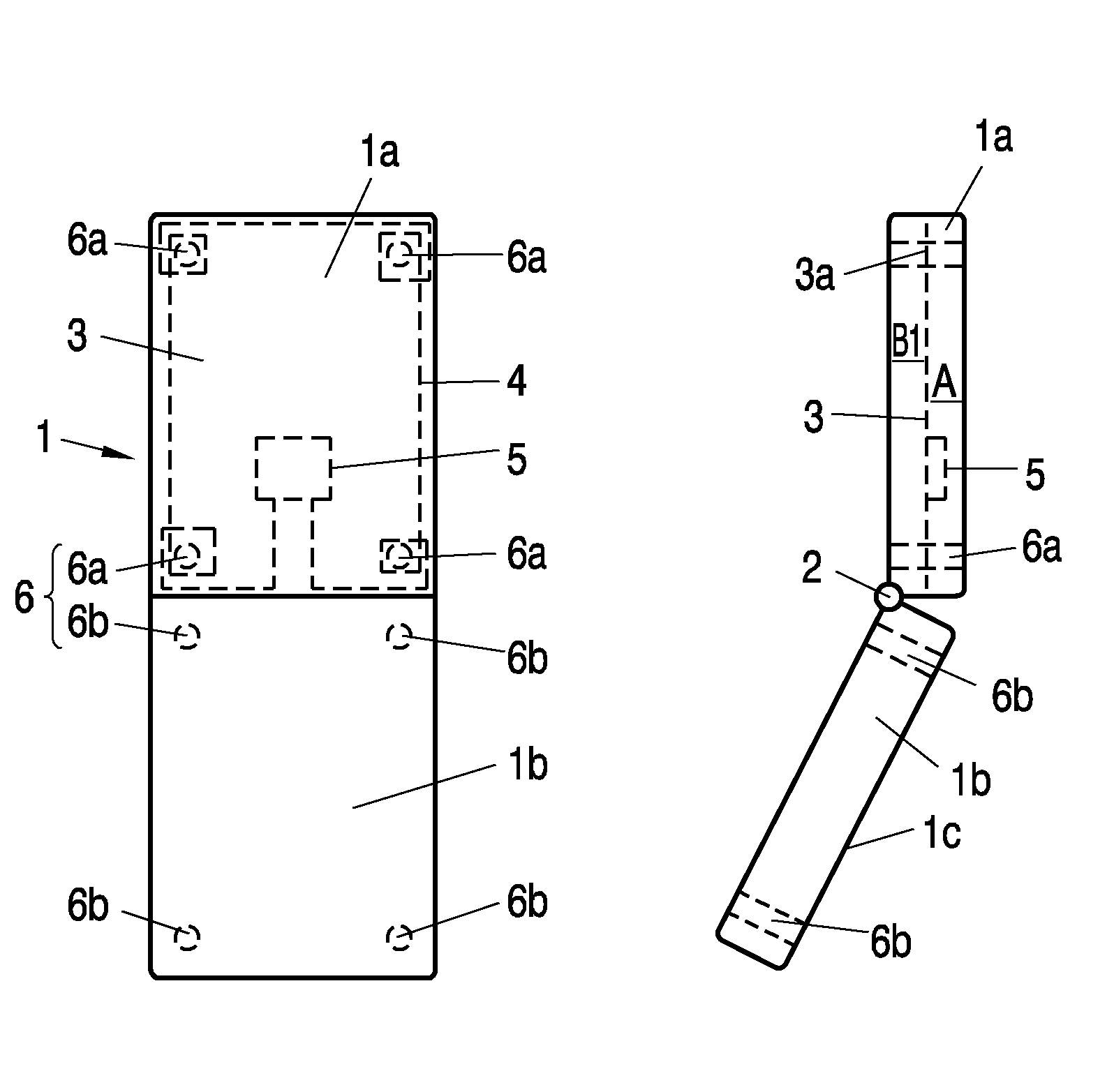
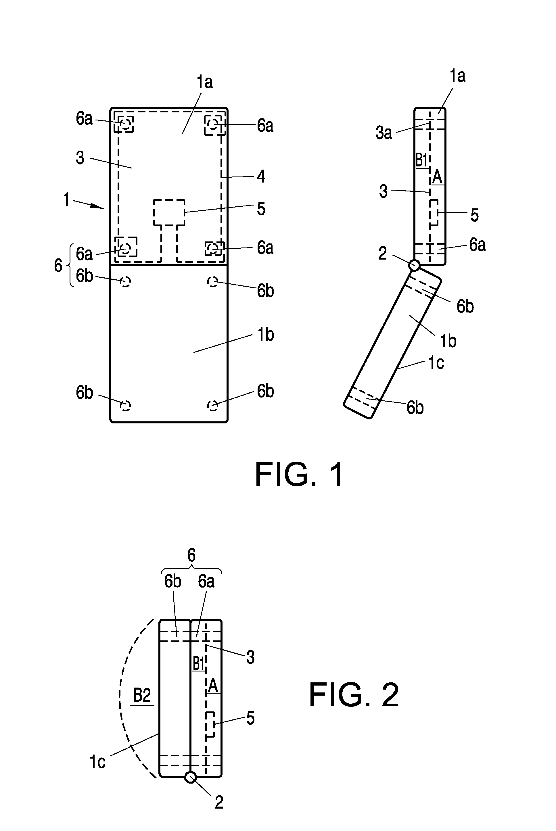
[0010]It is further advantageous, when said mobile communication device comprises a first device portion and a second device portion, which are displaceable in respect of each other between a first and a second operating position, wherein the ferrite is split into a first ferrite part being arranged in the first device portion and a second ferrite part being arranged in the second device portion, wherein in the first operating position said first and second ferrite parts are adjacent to each other and in the second operating position said first and second ferrite parts are interspaced. Hence reception and transmission of electromagnetic fields can be ensured in all areas of the mobile communication device even when the mobile communication device comprises two or more portions that are displaceable with respect to each other. Further, by splitting the ferrite into ferrite parts, a very compact but flexible structural shape of the communication device can be achieved.
[0011]It is further advantageous, when said first device portion and said second device portion are connected by means of a hinge, or by means of a slide. Thus a predefined first and second operating position is given, so that wireless communication works in both areas of the communication device irrespective of whether the device is opened or closed.
[0012]Yet another preferred embodiment of the invention is a mobile communication device, wherein the ferrite is a ferrite rod split into first and second ferrite parts transverse to its longitudinal axis, and the first and second ferrite parts are arranged in the first device portion and second device portion in such a manner that in the first operation position they are arranged coaxially. Therefore the advantage that the ferrite parts complement each other to a ferrite rod that guides a magnetic flux with high efficiency is provided, since the respective axes of the ferrite parts coincide and the adjacent faces of the ferrite parts are abutting so that magnetic losses are minimized.
[0017]These measures provide the advantage that the production process of such a device can be highly automated and is applicable to PCB mounting processes. Further, a single antenna can generate a magnetic flux in a plurality of ferrites. By directing the electrical conductor of the antenna as proposed in the aforesaid manner, losses of magnetic flux are kept very low and the electromagnetic field is concentrated in the regions where the ferrites are positioned.

Problems solved by technology

The known wireless audio communications system and the known RF communication system, however, have shown the disadvantage that they only consider external interference and nulls of the electromagnetic fields between a transceiver unit (transponder unit) and a base unit transceiver (interrogation unit), but disregard completely interference or nulls of the electromagnetic fields that are caused by the construction of one or both of the devices communicating with each other.
However, the inventors have recognized that insufficient reception and transmission of electromagnetic signals is very often caused by unwanted shielding of electromagnetic signals within a communication device or between internal and external areas by components of this device.
This problem increases when the mobile communication device, such as a mobile telephone, is equipped with additional RF communication means like RFID readers / writers, RFID tags or Near Field Communication (NFC) devices.

Method used


Image

  • Mobile Communication Device
  • Mobile Communication Device
  • Mobile Communication Device

Examples


Embodiment Construction

[0025]FIG. 1 shows a first mobile communication device 1 according to the invention. This mobile communication device 1 is of the so-called clamshell device type having a first and a second device portion 1a, 1b, which are linked together by means of a hinge 2. It should be observed that clamshell devices are also known as flip cover devices, such as flip mobile phones. In the present embodiment first device portion 1a constitutes a body of the mobile communication device 1, and second device portion 1b constitutes a corresponding cover. The first and second device portion 1a and 1b are moveable relative to each other between a first and a second operating position depicted in FIG. 1. In the first operating position, which is a closed operating position, the two device portions 1a, 1b are positioned adjacent to each other in such a manner that second device portion 1b, i.e. the cover completely covers one side of the first device portion 1a, i.e. the body. In the second operating po...


PUM


Abstract

A mobile communication device (1, 10) comprises shielding components that provide electromagnetic shielding or attenuation between a first area (A) and a second area (B, B1, B2) within and / or external of the communication device (1, 10). In said first area (A) an antenna (4) and at least one ferrite (6) are arranged, which ferrite (6) is provided to interact with said antenna (4) and to guide a magnetic flux between said first area (A) and said second area (B, B1, B2).

Description

FIELD OF THE INVENTION[0001]The invention relates to a mobile communication device comprising shielding components, which cause electromagnetic shielding or attenuation between a first area and a second area within and / or external of the communication device.BACKGROUND OF THE INVENTION[0002]From document WO 98 / 52295 a short-range wireless audio communications system is known, including a miniaturized portable transceiver unit and a base unit transceiver. The miniaturized portable transceiver unit sends and receives information through magnetic induction to the base unit, which may also be portable. Similarly, the base unit sends and receives information through magnetic induction to the portable transceiver. The use of magnetic induction fields limits interference between a plurality of systems operating in close proximity to each other, and it reduces the power requirements. Each of the transducers preferably is a rod antenna such as a ferrite rod within a wire coil. In an embodime...

Claims


Application Information

Patent Timeline
IPC IPC(8): H04M1/03H04M1/00
CPCH01Q1/243H04B5/02H04B5/0081H01Q1/526H04B5/26H04B5/48
Inventor SCHAFFLER, GERALD
Owner NXP BV
Learn More