System and Method For Optical Position Measurement And Guidance Of A Rigid Or Semi-Flexible Tool To A Target

a technology of optical position measurement and guidance, applied in the field of optical tracking systems, can solve the problems of erroneous location determination of the distal tip of the needle, small diameter bending, and inability to achieve the accuracy that could be achieved by using an intermediate system of coordinates in the determination of the position of the tool relative to the body

Active Publication Date: 2008-08-28
STRYKER EURO OPERATIONS HLDG LLC
View PDF3 Cites 93 Cited by
  • Summary
  • Abstract
  • Description
  • Claims
  • Application Information

AI Technical Summary

Benefits of technology

[0041]There is also provided according to the teachings of the present invention, a patch for attachment to the skin of a body for use together with an optical guidance system for guiding a distal end of a rigid or semi-flexible tool to a target within a body, the tool having a proximal portion for manual manipulation from outside the body, the patch comprising: (a) a lower surface for adhering temporarily to the skin; (b)...

Problems solved by technology

Since each position determination inherently adds some location error to the process, using an intermediate system of coordinate in determination of the position of the tool relative to the body is less accurate than could possibly be achieved by direct measurement of the position of the tool in body system of coordinates.
However, needles, because of their small diameters tend to bend.
Particularly when pushed percutaneously towards a target, the forces applied to manipulate and advance the needle ...

Method used


Image

  • System and Method For Optical Position Measurement And Guidance Of A Rigid Or Semi-Flexible Tool To A Target
  • System and Method For Optical Position Measurement And Guidance Of A Rigid Or Semi-Flexible Tool To A Target
  • System and Method For Optical Position Measurement And Guidance Of A Rigid Or Semi-Flexible Tool To A Target

Examples


Embodiment Construction

[0056]The present invention is a system and method for optical position measurement and guidance of a rigid or semi-flexible tool to a target.

[0057]The principles and operation of systems and methods according to the present invention may be better understood with reference to the drawings and the accompanying description.

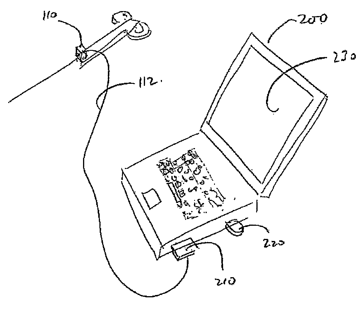
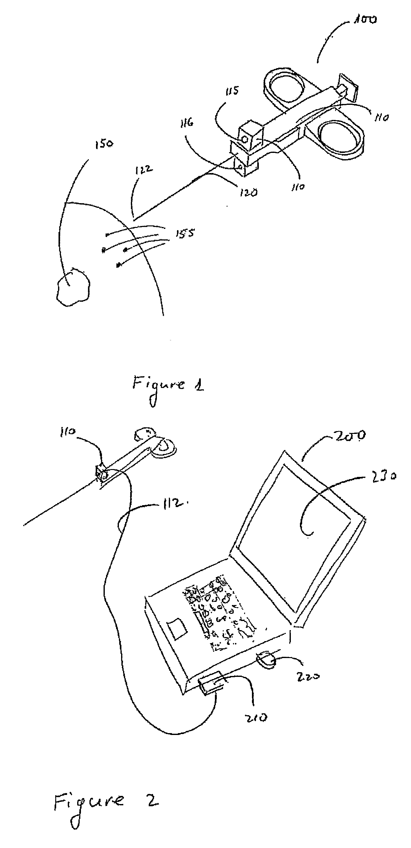
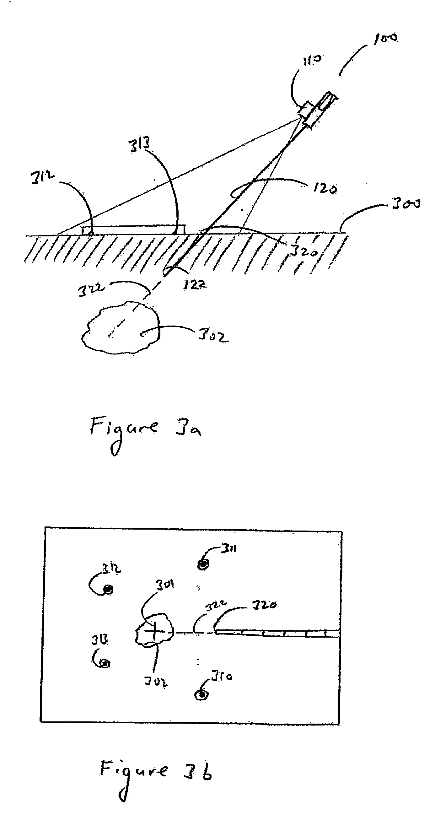
[0058]Generally speaking, the present invention provides a system for measuring the position of a hand-held tool relative to a body in at least five degrees of freedom. The system operates with a rigid or semi-flexible tool having a distal end for insertion into the body, and a proximal portion for manual manipulation outside the body. A camera for generating images is attached via a mechanical linkage to the tool such that the camera moves together with the proximal portion of the tool, and that the camera is directed with a field of view including the distal end of the tool. A processing system in data communication with the camera and configured to process image...


PUM


Abstract

A system for measuring the position of a hand-held tool relative to a body in six degrees of freedom employs a camera attached via a mechanical linkage to the tool so that the camera moves together with the proximal portion of the tool and has a field of view including the distal end of the tool. A processing system processes images from the camera to determine a position of at least part of the tool. By employing optically identifiable fiducial reference points defined on the external surface of the body, a projection of the tool tip position onto a plane containing the target can be derived and displayed together with the target position, thereby facilitating guiding the tool to the target.

Description

FIELD AND BACKGROUND OF THE INVENTION[0001]The present invention relates to optical tracking systems and, in particular, it concerns a system and method for optical position measurement and guidance of a rigid or semi-flexible tool to a target.[0002]Needle tools are often used in the medical field to deliver local treatment. In recent years, these procedures are carried by interventional radiologists, physicians who are experts in using imaging devices for guiding and controlling diagnostics and therapeutic procedures. In these procedures, the needles are inserted into the body under control of the imaging device.[0003]Since the energy used by CT and fluoroscopy is X-ray, which is ionizing and harmful to living organs, image guided systems have been developed for navigating tools to a target based on preoperative CT data. Such navigation systems measure the location of the body and the location of the tool in six degrees of freedom and, by subtracting tool location from body locatio...

Claims


Application Information

Patent Timeline
IPC IPC(8): A61B5/05
CPCA61B6/12A61B19/201A61B19/5212A61B19/5244A61B2019/502A61B2019/507G06T2207/30208A61B2019/5255A61B2019/5265A61B2019/5272G06T7/0042G06T2207/30004G06T2207/30021A61B2019/5227A61B2034/102A61B2034/2055A61B2034/2072A61B34/20A61B90/361A61B90/11A61B2034/107A61B2090/371A61B2034/2065G06T7/73G06T7/20G06T7/00
Inventor GILBOA, PINHAS
Owner STRYKER EURO OPERATIONS HLDG LLC
Why Eureka
Try Eureka