Sealed capacitive sensor

a capacitive sensor and sealing technology, applied in the direction of fluid pressure measurement, fluid pressure measurement by electric/magnetic elements, instruments, etc., can solve the problems of diaphragms being more susceptible to cracking and fracturing, reducing sensitivity, and reducing sensitivity, so as to reduce the risk of contamination, and the effect of reliability and accuracy

Inactive Publication Date: 2008-09-04
ANALOG DEVICES INC
View PDF34 Cites 8 Cited by
  • Summary
  • Abstract
  • Description
  • Claims
  • Application Information

AI Technical Summary

Benefits of technology

[0007]It is a further object of this invention to provide such an improved sealed capacitive sensor which is more robust, reliable and accurate, yet lower in cost.
[0008]It is a further object of this invention to provide such an improved sealed capacitive sensor in which the dielectric gap is not vulnerable to fracture, breakage or creep of solder balls.
[0009]It is a further object of this invention to provide such an improved sealed capacitive sensor which is less susceptible to contamination.
[0010]The invention results from the realization that a simpler, less costly, more accurate, reliable and robust capacitive sensor can be achieved by using a sealing medium such as a frit or glass frit to both connect together and hermetically seal a substrate having a diaphragm forming a first plate of a capacitor and a second fixed plate of a capacitor spaced from the diaphragm and defining a predetermined dielectric gap.

Problems solved by technology

One problem with this is that the solder balls are typically about 150-200 μm in height.
With such a large height the gap, too, is large and this reduces the sensitivity.
This makes the diaphragm more susceptible to cracking and fracturing.
One solution is to provide holes to receive the solder balls and thus reduce their effective height.
But the addition of these holes adds considerable cost and must be done extremely accurately.
Even assuming a proper balance between solder ball height and diaphragm thickness can be obtained, the solder balls themselves contribute to inaccuracy as they may fracture, break and are subject to creep from temperature and time.
To accommodate this the entire device can be placed in a sealed package but this, too, adds to the cost.

Method used


Image

  • Sealed capacitive sensor
  • Sealed capacitive sensor
  • Sealed capacitive sensor

Examples


Embodiment Construction

[0026]Aside from the preferred embodiment or embodiments disclosed below, this invention is capable of other embodiments and of being practiced or being carried out in various ways. Thus, it is to be understood that the invention is not limited in its application to the details of construction and the arrangements of components set forth in the following description or illustrated in the drawings. If only one embodiment is described herein, the claims hereof are not to be limited to that embodiment. Moreover, the claims hereof are not to be read restrictively unless there is clear and convincing evidence manifesting a certain exclusion, restriction, or disclaimer.

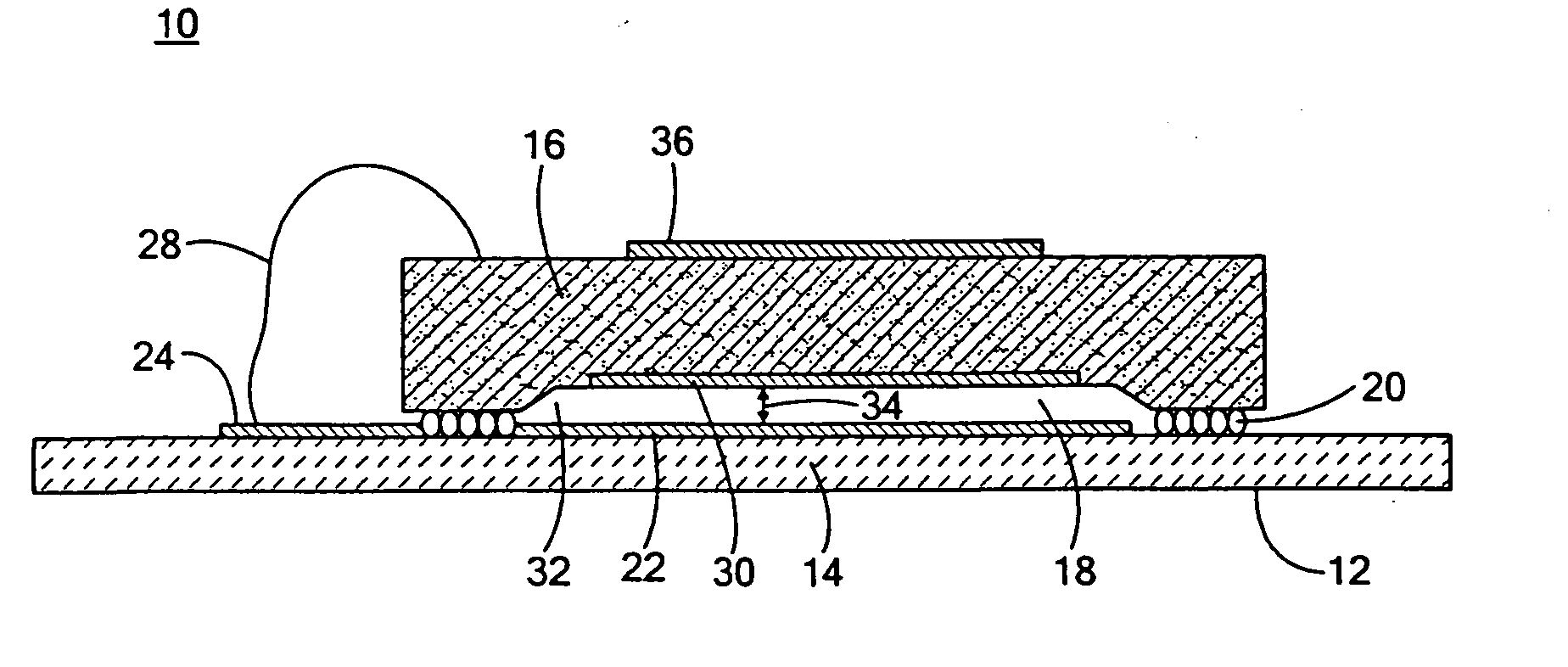
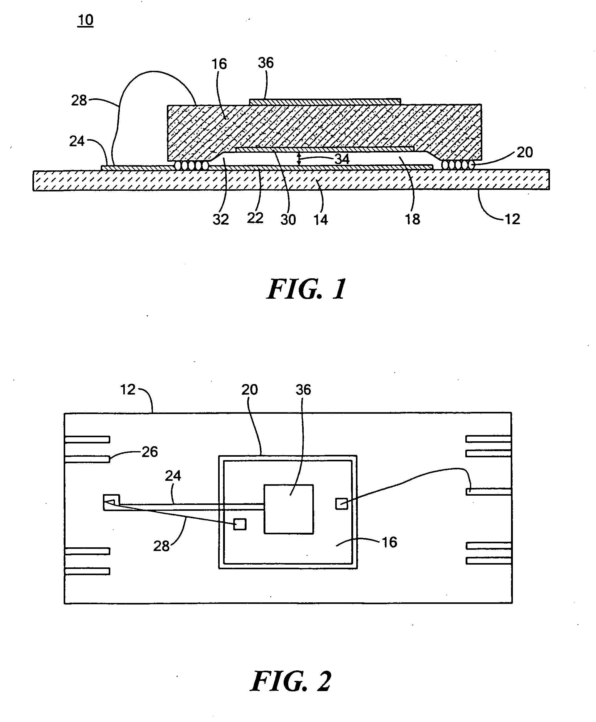
[0027]There is shown in FIG. 1, a sealed capacitive sensor 10 including a ceramic substrate 12, for example, Al2O3 having a flexible diaphragm 14 and a fixed plate silicon die 16 spaced from diaphragm 14 defining a dielectric gap 18. Substrate 12 is connected to fixed plate or die 16 to form an integral structure by means o...


PUM

PropertyMeasurementUnit
heightaaaaaaaaaa
thickaaaaaaaaaa
thickaaaaaaaaaa

Abstract

A sealed capacitive sensor includes a substrate having a diaphragm forming a first plate of a capacitor; a second fixed plate of the capacitor spaced from the diaphragm and defining a predetermined dielectric gap and a sealing medium connecting together the substrate and fixed plate in an integrated structure and hermetically sealing the gap.

Description

RELATED APPLICATIONS[0001]This application is a continuation of patent application Ser. No. 11 / 353,359, filed Feb. 14, 2006, and claims the benefit of U.S. Provisional Application No. 60 / 656,238, filed Feb. 25, 2005, incorporated by reference herein.FIELD OF THE INVENTION[0002]This invention relates to a sealed capacitive sensor.BACKGROUND OF THE INVENTION[0003]In conventional capacitive sensors the fixed plate, typically silicon, is connected to the diaphragm, typically formed in a ceramic substrate, using solder balls. One problem with this is that the solder balls are typically about 150-200 μm in height. This defines at least in part the dimension of the capacitive gap. With such a large height the gap, too, is large and this reduces the sensitivity. Therefore the diaphragm has to deflect more under pressure to obtain the desired sensitivity. To accommodate this the diaphragm must be made thinner to get the desired sensitivity. This makes the diaphragm more susceptible to cracki...

Claims


Application Information

Patent Timeline
Patent Type & Authority Applications(United States)
IPC IPC(8): G01L1/14
CPCG01L1/142G01L1/148G01L9/0075G01L9/0073G01L9/0072H01L2224/48091H01L2224/73257H01L2924/00014
Inventor MEEHAN, PETER G.HUNT, WILLIAMHYNES, EAMONO'DOWD, JOHNKIERSE, OLIVER
Owner ANALOG DEVICES INC
Why Eureka
Try Eureka