Composite article debulking process

a technology of composite articles and debulking processes, which is applied in the field of fiber reinforced composite structure and articles, can solve the problems of air trapped between the layers of prefabricated materials, air trapped, and discontinuities in the final cured material or part, and weakening the structur

Inactive Publication Date: 2008-09-04
PRESSURE SOLUTIONS INT
View PDF27 Cites 32 Cited by
  • Summary
  • Abstract
  • Description
  • Claims
  • Application Information

AI Technical Summary

Benefits of technology

[0009]The present invention provides an improved process for debulking uncured fiber reinforced composite structures and improved apparatus for debulking such structures.

Problems solved by technology

Both hand and mechanical lay-up processes can leave air trapped between the layers of plies of the prepreg materials.
If this are is not removed before the curing process of the material, the air may stay trapped and create discontinuities in the final cured material or part.
These discontinuities create inherent flaws in the material which may weaken the structure or reduce the quality of the part.
Further, volatiles trapped in the matrix or resin of the composite materials may also become trapped during the curing process.
These trapped volatiles may also contribute to discontinuities and porosity.
While conventional processes for debulking composite structures prior to curing may be adequate for structures used in non-critical applications and in terrestrial environments, conventional process tend to leave some voids within the structures.
When composite structures formed by conventional processes are placed in more critical applications, such as in components for aerospace applications, the extreme environments and loads that the structures are subjected to reveal the weaknesses caused by such voids and porosities in accelerated breakdown of the components and occasionally in catastrophic failures.

Method used


Image

  • Composite article debulking process
  • Composite article debulking process
  • Composite article debulking process

Examples


Embodiment Construction

[0017]As required, detailed embodiments of the present invention are disclosed herein; however, it is to be understood that the disclosed embodiments are merely exemplary of the invention, which may be embodied in various forms. Therefore, specific structural and functional details disclosed herein are not to be interpreted as limiting, but merely as a basis for the claims and as a representative basis for teaching one skilled in the art to variously employ the present invention in virtually any appropriately detailed structure.

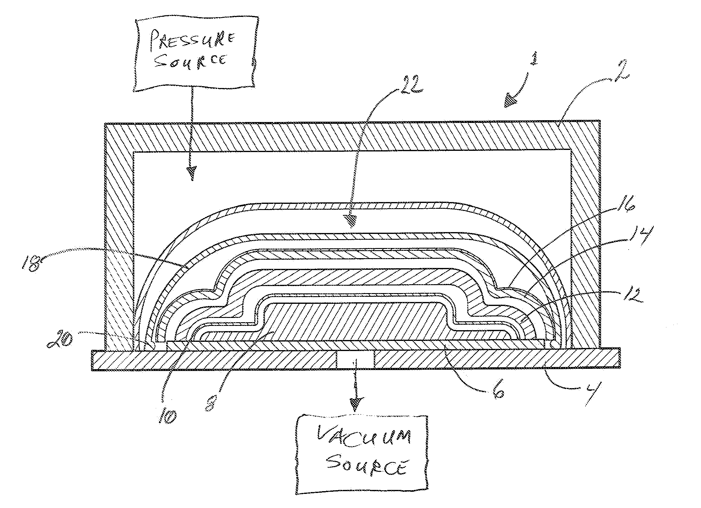
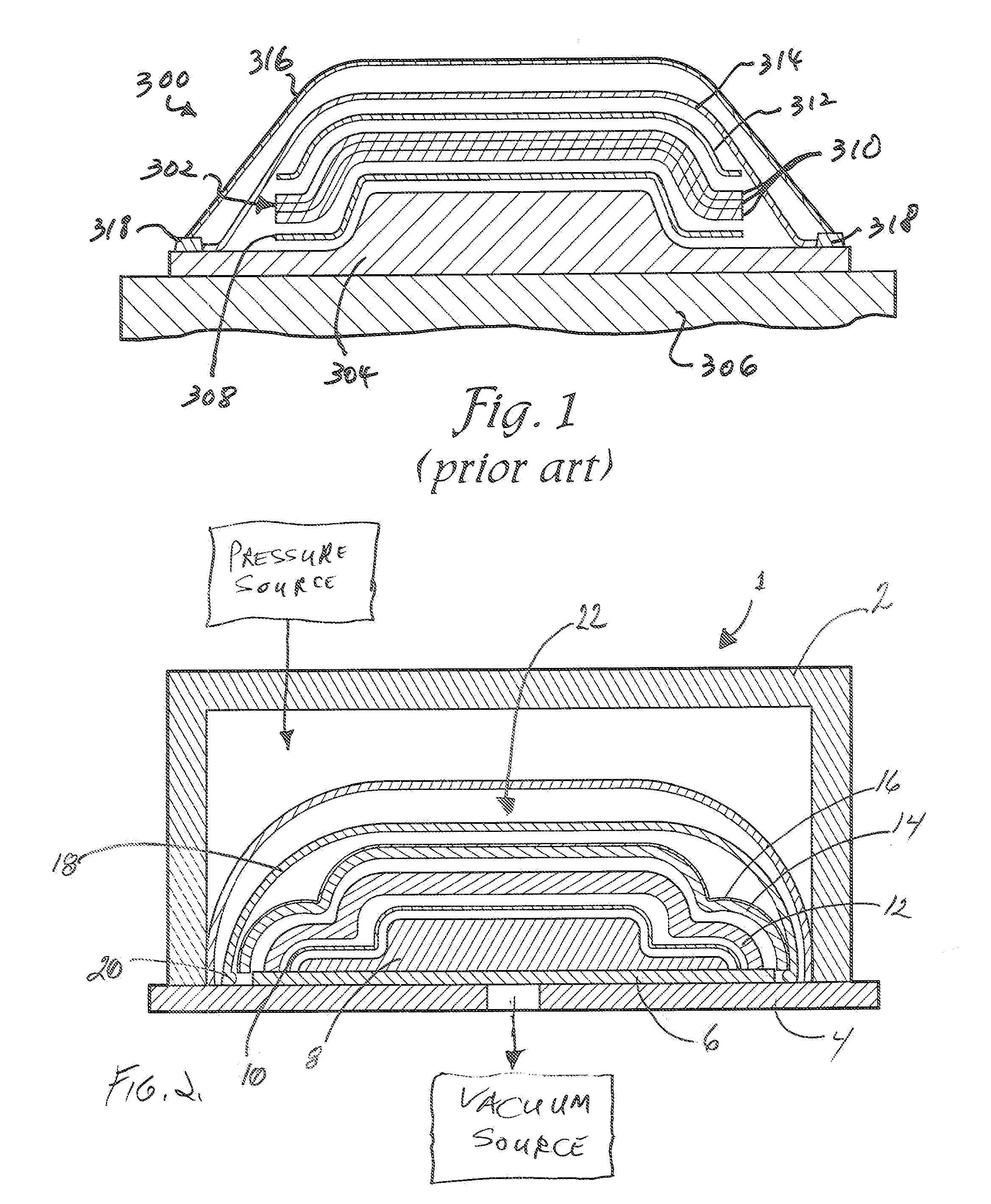
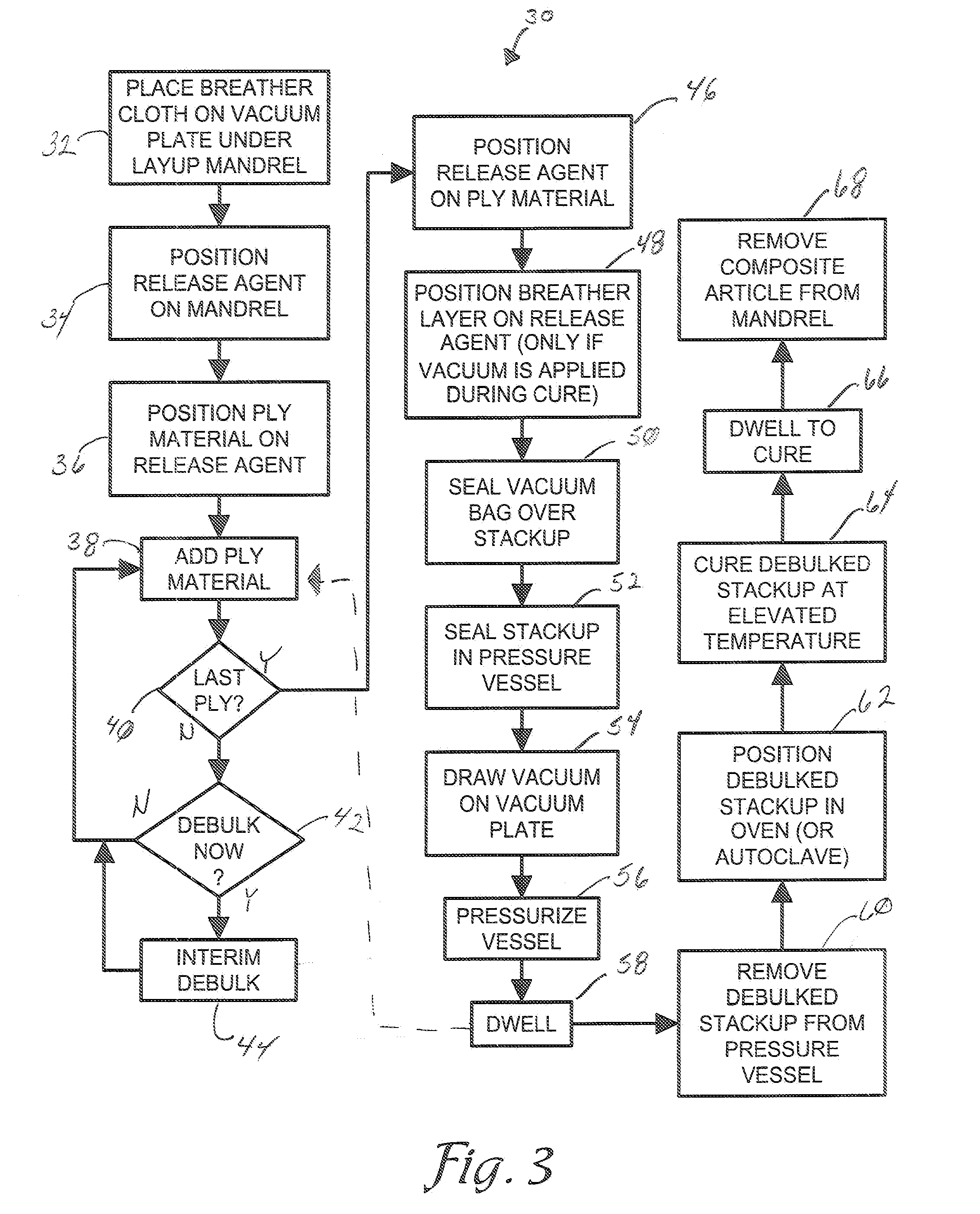
[0018]Referring now to the drawing figures, the reference numeral 1 refers to an improved debulking chamber in accordance with the invention, which is depicted in FIGS. 1 and 4 in association with an improved debulking process shown in FIG. 3.

[0019]As best shown in FIG. 2, improved debulking chamber 1 is comprised of a pressure vessel 2, capable of pressures ranging from 1 to 20 or more atmospheres. Improved debulking chamber 1, also utilizes a vacuum plate 4...


PUM

PropertyMeasurementUnit
pressureaaaaaaaaaa
temperatureaaaaaaaaaa
pressureaaaaaaaaaa

Abstract

A process for debulking a fiber reinforced composite structure prior to curing includes forming a stackup of a breather pad on a vacuum plate, a mandrel on the breather pad, a first release layer on the mandrel, a plurality of prepreg plies on the release first layer, a second release layer on the top ply, a breather sheet on the second release layer, and an impervious flexible vacuum bag sealed over the breather sheet to the vacuum plate; sealingly enclosing the stackup within a pressure vessel including an impervious flexible membrane which engages the vacuum bag; drawing a vacuum from within the vacuum bag through the breather pad and the vacuum plate; pressurizing the pressure vessel between the shell and the membrane; and maintaining the combination of vacuum and pressure for an interval of time to remove voids and porosity from the laminated prepregs.

Description

CROSS-REFERENCE TO RELATED APPLICATION[0001]This application claims priority under 35 U.S.C. 119(e) and 37 C.F.R. 1.78(a)(4) based upon copending U.S. Provisional Application Ser. No. 60 / 904,271 for APPARATUS AND METHOD FOR DEBULKING A COMPOSITE MATERIAL, filed Mar. 1, 2007, and which is incorporated herein by reference.BACKGROUND OF THE INVENTION[0002]The present invention is generally directed to the manufacture of fiber reinforced composite structures and articles and, more particularly, to methods and apparatus for debulking such structures to remove porosity defects and discontinuities from such structures, which result from gases and gas voids within such structures at interim stages of the manufacture thereof.[0003]Composite materials or composites are engineered materials made from two or more constituent materials with significantly different physical and / or chemical properties and which remain separate and distinct within the finished structure but which cooperate to form ...

Claims


Application Information

Patent Timeline
Patent Type & Authority Applications(United States)
IPC IPC(8): B29C65/00
CPCB29C70/44
Inventor CUMINGS, ROBERT C.VANDERBOS, TERENCE GERARD
Owner PRESSURE SOLUTIONS INT
Why Eureka
Try Eureka