Method of Generating Fault Indication in Feeder Remote Terminal Unit for Power Distribution Automation System

Inactive Publication Date: 2008-09-04
MYONGJI UNIV IND & ACAD COOPERATION FOUND
View PDF0 Cites 91 Cited by
  • Summary
  • Abstract
  • Description
  • Claims
  • Application Information

AI Technical Summary

Benefits of technology

[0019]In addition, the present invention provides a method of generating fault indication in a feeder remote terminal unit for a power distribution automation system in a method of detecting a faulty section in a distribution system, the distribution system including a plurality of feeder remote terminal units, which are installed in respective sections of a line and are configured to measure voltage, current and a phase difference of the line, a fault line detection unit for detecting whether a fault occurs in the line, a central control unit for determining whether a fault occurs through the feeder remote termina

Problems solved by technology

And when a single-line ground fault occurs, an intermittent arc ground fault is caused by charge current, and thus an abnormal voltage is generated.
Further, when a single-line ground fault occurs, the magnitude of fault current is equal to or less than several amperes, so that the detection of a fault is difficult, and thus it is difficult to predict the precise operation of a ground fault protection relay.
Further, when protection fails, the range of the ground fault may increase, and the ground fault may develop into a short circuit fault.
Such an operation requires a lot of manpower and high costs associated with outage.
When a fault occurs in power equipment in the distribution system, high fault current flows from a power stage to a fault location.
After the fault removal operation has been completed, a wide outage occurs in distribution sys

Method used


Image

  • Method of Generating Fault Indication in Feeder Remote Terminal Unit for Power Distribution Automation System
  • Method of Generating Fault Indication in Feeder Remote Terminal Unit for Power Distribution Automation System
  • Method of Generating Fault Indication in Feeder Remote Terminal Unit for Power Distribution Automation System

Examples


Embodiment Construction

[0031]Hereinafter, embodiments of the present invention will be described in detail with reference to the attached drawings.

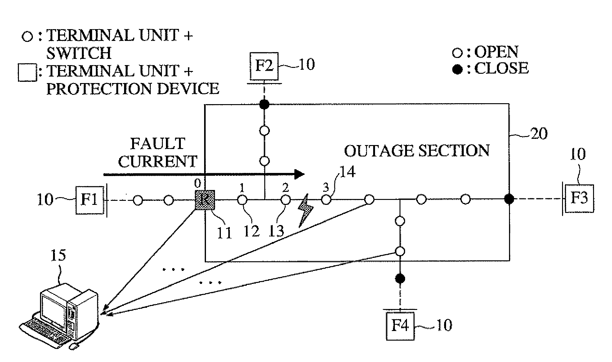
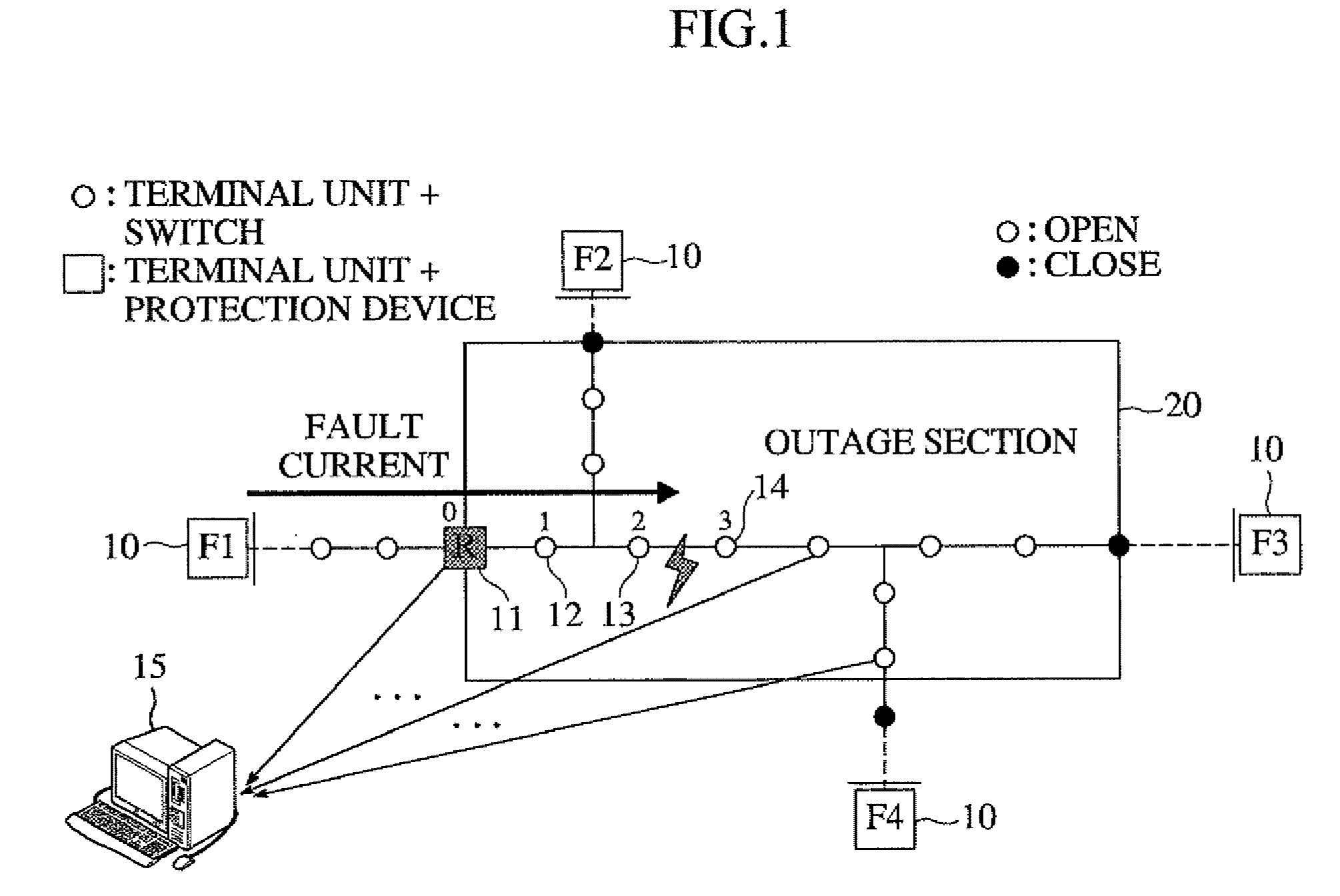
[0032]FIG. 1 is a block diagram showing an example of a system for determining a faulty section from fault indication information according to the present invention. FIG. 1 illustrates a power distribution automation system that is configured to include a first feeder remote terminal unit 11, a second feeder remote terminal unit 12, a third feeder remote terminal unit 13, a fourth feeder remote terminal unit 14, and a fault line detection unit 10, which are installed on a line, and a central control unit 15, and that is configured to find and isolate a faulty section and switch a sound section placed downstream of the faulty section over to a tieline, thus continuing to supply power to all loads without interrupting the supply of power.

[0033]The first feeder remote terminal unit 11 includes a protection device, and each of the second feeder remote terminal unit...


PUM


Abstract

The present invention relates to a method of generating fault indication in a feeder remote terminal unit for a power distribution automation system. The method is performed in a distribution system that includes a plurality of feeder remote terminal units, which are installed in respective sections of a line and are configured to measure voltage, current and a phase difference of the line, and a central control unit for determining whether a fault occurs and controlling operation of the feeder remote terminal units. In the method, phases are measured by each of the feeder remote terminal units. The phase of a zero-sequence current is compared with that of a zero-sequence voltage. A direction of a fault current is calculated, and fault indication information is generated in the calculated direction of the fault current.

Description

BACKGROUND OF THE INVENTION[0001]1. Field of the Invention[0002]The present invention relates, in general, to a method of generating fault indication in a feeder remote terminal unit for a power distribution automation system, and, more particularly, to a method of generating fault indication in a feeder remote terminal unit for a power distribution automation system, which obtains both the phase of a zero-sequence voltage and the phase of a zero-sequence current, and generates fault indication information when the phases satisfy certain conditions.[0003]2. Description of the Related Art[0004]Generally, in a distribution system, an ungrounded method is used in a system having a short line and a low voltage. In such a line, since ground capacitance is low, charge current is not high. When a single-line ground fault occurs in the line of an ungrounded system, fault current, attributable to ground capacitance having a sound phase, flows into a fault point, but the magnitude of the faul...

Claims


Application Information

Patent Timeline
IPC IPC(8): G01R31/08
CPCG01R31/086Y04S10/522H02H3/385H02H3/081Y04S10/52H02H3/38H02H7/26
Inventor CHOI, MYEON SONGLIM, SEONG ILLEE, SEUNG JAE
Owner MYONGJI UNIV IND & ACAD COOPERATION FOUND
Why Eureka
Try Eureka