Liquid Crystal Display and Gate Driving Circuit Thereof

a technology of gate driving circuit and liquid crystal display, which is applied in the field of liquid crystal display and gate driving circuit thereof, can solve the problems of increasing the fabrication cost insufficient charge of pixels, and insufficient space for the integration of the lcd panel

Inactive Publication Date: 2008-09-04
SAMSUNG DISPLAY CO LTD
View PDF6 Cites 56 Cited by
  • Summary
  • Abstract
  • Description
  • Claims
  • Application Information

AI Technical Summary

Benefits of technology

[0010]In accordance with the exemplary embodiments described herein, an LCD and a gate driving circuit are provided that require fewer signal lines to be connected to the gate driving circuit inter alia, by sharing the start pulse of a dual gate driving circuit and an output signal of a dummy stage.

Problems solved by technology

In the single driving type LCD, gate driving signals output from the left and right gate driving circuits are delayed toward the ends of the gate lines causing some of the pixels to be insufficiently charged thereby resulting in a horizontal line visibility phenomenon.
However, the foregoing approach requires twice as many signal lines as in the single driving type LCD and thus more space is required for integration of the LCD panel and increasing fabricating costs of the LCD panel.

Method used


Image

  • Liquid Crystal Display and Gate Driving Circuit Thereof
  • Liquid Crystal Display and Gate Driving Circuit Thereof
  • Liquid Crystal Display and Gate Driving Circuit Thereof

Examples


Embodiment Construction

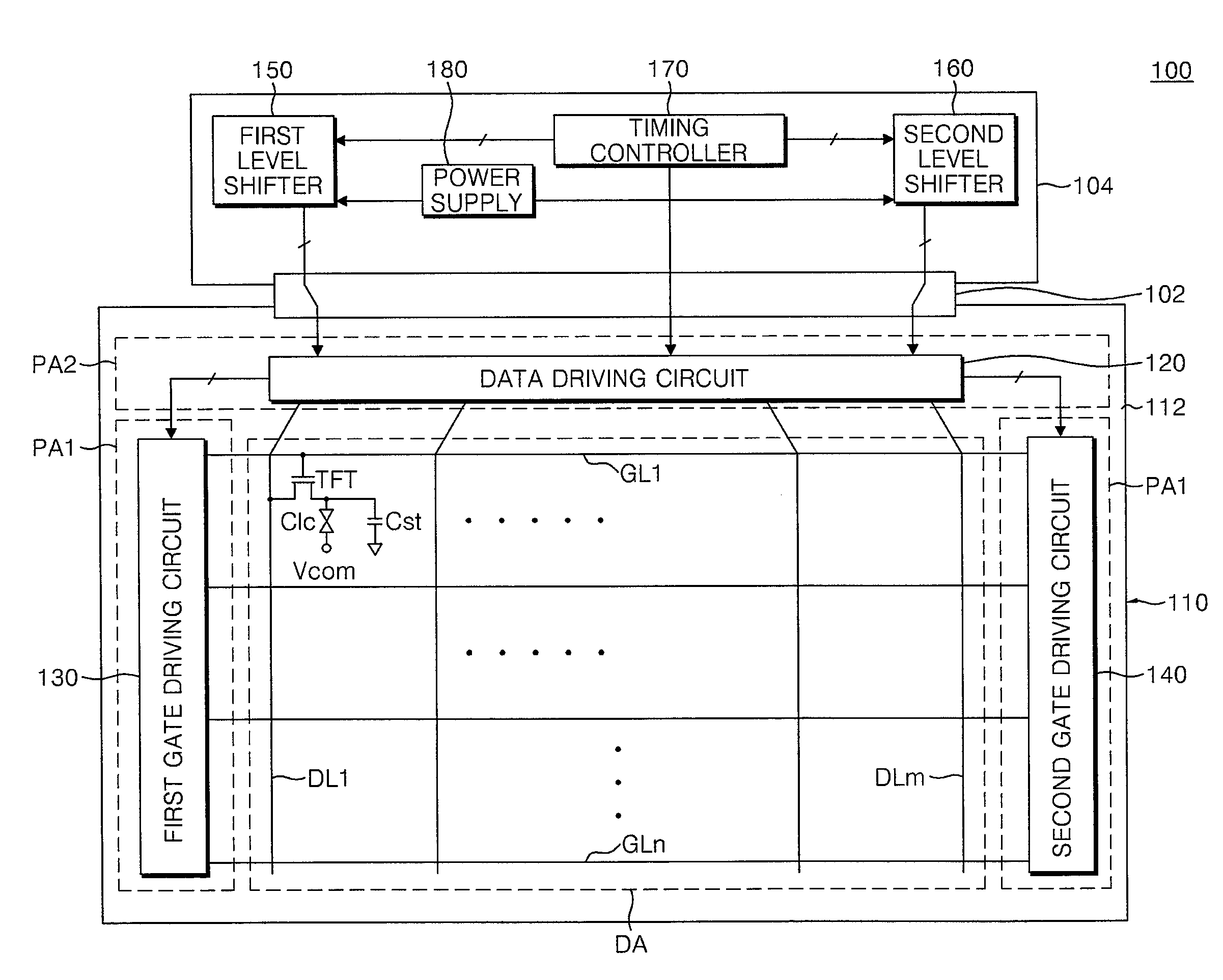
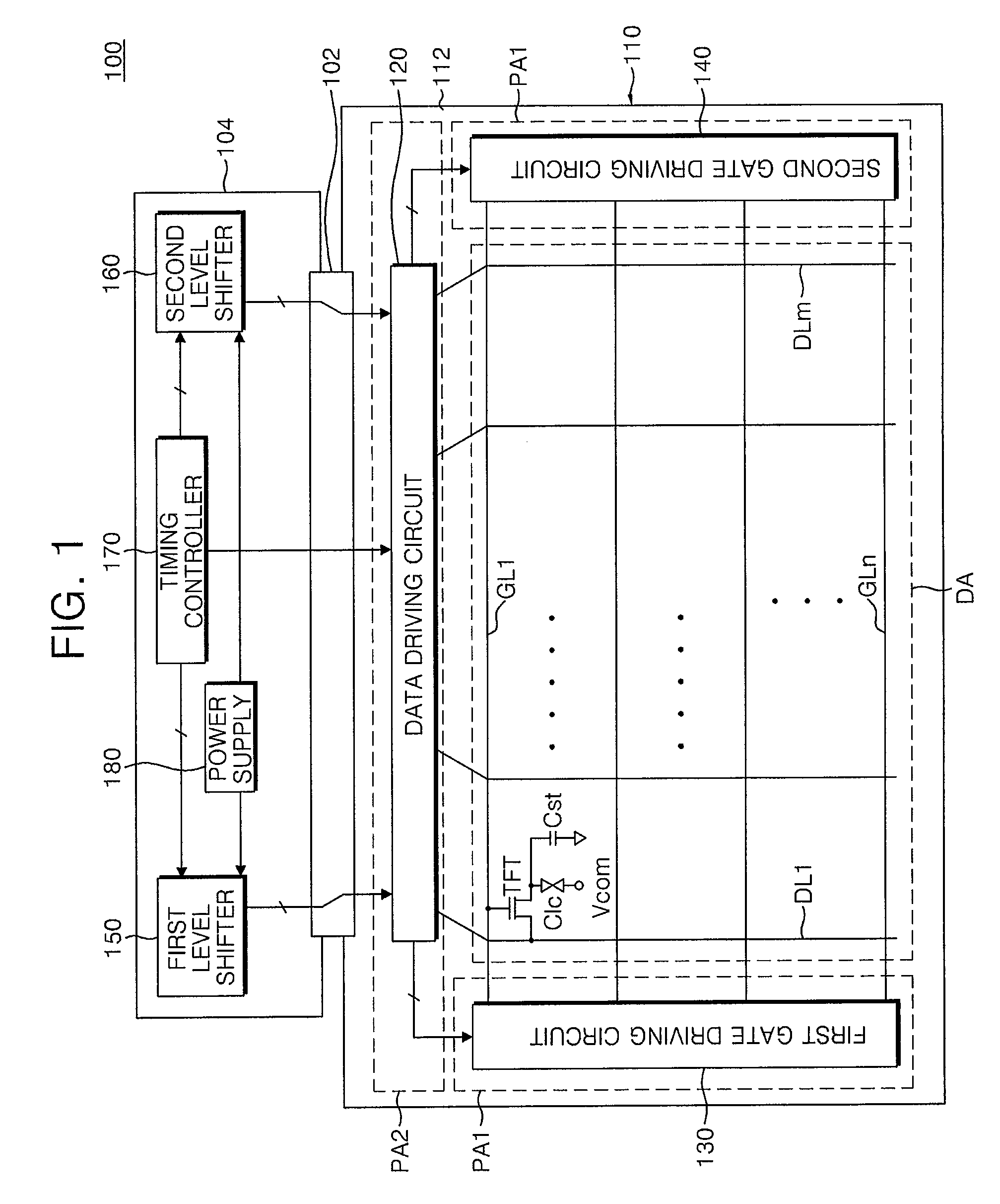
[0022]FIG. 1 is a block diagram of an LCD according to one embodiment of the present invention.

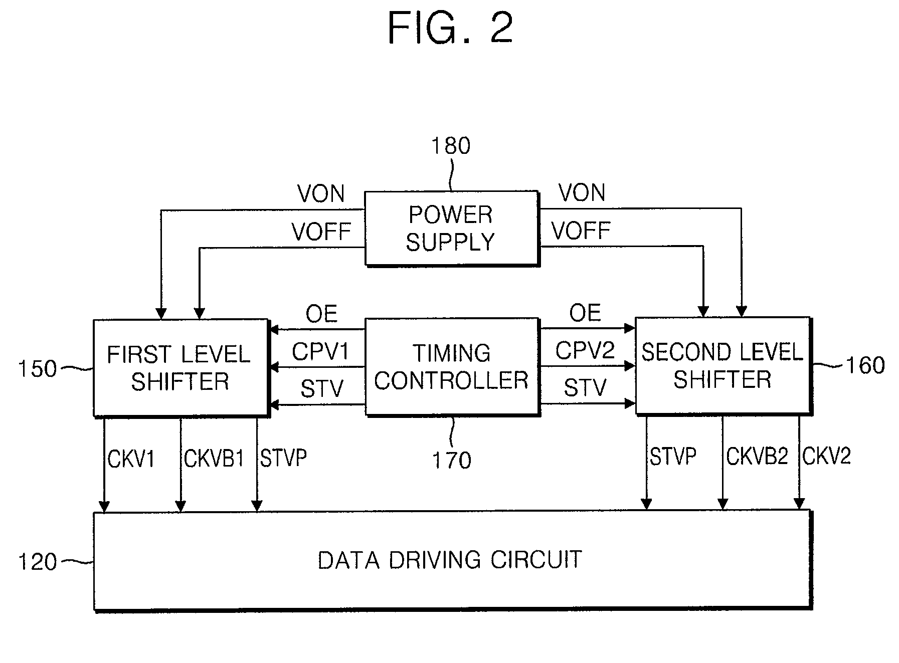
[0023]Referring to FIG. 1, an LCD 100 according to an exemplary embodiment of the present invention includes an LCD panel 110, a data driving circuit 120, a first gate driving circuit 130, a second gate driving circuit 140, a first level shifter 150, a second level shifter 160, a timing controller 170, and a power supply 180.

[0024]The LCD panel 110 includes a TFT substrate 112, a color filer substrate (not shown), and a liquid crystal layer (not shown) disposed between the TFT substrate 112 and the color filter substrate.

[0025]The TFT substrate 112 includes a display area DA, first peripheral areas PA1, and a second peripheral area PA2. The display area DA is provided with gate lines GL1 to GLn, data lines DL1 to DLm, and pixels connected to the gate lines GL1 to GLn and the data lines DL1 to DLm, respectively. The first peripheral areas PA1 is provided with the first and second gate drivi...


PUM


Abstract

A liquid crystal display and a dual gate driving circuit therefor wherein the number of signal lines are reduced by sharing a start pulse and an output signal of a dummy stage. The liquid crystal display includes a timing controller generating an output enable signal, a gate clock, and a signal start signal in response to an external input signal, a level shifter generating a gate clock pulse and a gate clock bar pulse in response to the output enable signal and the gate clock and generating a single start pulse in response to the start signal and the gate clock, and first and second gate driving circuits outputting the gate clock pulse or the gate clock bar pulse as a gate driving signal to the plurality of gate lines in response to the single start pulse.

Description

CROSS-REFERENCE TO RELATED APPLICATIONS[0001]This application claims priority of Korean Patent Applications Nos. 10-2006-0125333 and 10-2006-0129732, filed on Dec. 11, 2006 and Dec. 19, 2006, respectively, the entire contents of which are incorporated by reference herein.BACKGROUND OF THE INVENTION[0002]1. Field of the Invention[0003]The present invention relates to a liquid crystal display (LCD), and more particularly, to an LCD and gate driving circuit thereof.[0004]2. Discussion of the Related Art[0005]LCDs include an LCD panel for displaying an image, and data and gate driving circuits for driving the LCD panel. The LCD panel includes a plurality of gate lines, data lines, and pixels. Each pixel includes a thin film transistor (TFT) and a liquid crystal capacitor. The data driving circuit outputs data signals to the data lines and the gate driving circuit outputs gate driving signals to gate lines.[0006]The gate driving circuit is formed on the LCD panel simultaneously with and ...

Claims


Application Information

Patent Timeline
Patent Type & Authority Applications(United States)
IPC IPC(8): G09G3/36
CPCG09G3/3677G11C19/184G09G2320/0223G09G2310/0286
Inventor BAEK, SEUNG-SOOLEE, YONG SOONLEE, MIN CHEOLKIM, YOUNG BUMJEON, SANG JIN
Owner SAMSUNG DISPLAY CO LTD
Why Eureka
Try Eureka