Differential signaling system and flat panel display with the same

a signaling system and flat panel technology, applied in the field of flat panel display, can solve the problems of unstable wave, unstable wave, signal distortion and attenuation, and cannot be used, and achieve the effect of stably transmitting a high-speed signal

Active Publication Date: 2008-09-04
SAMSUNG DISPLAY CO LTD
View PDF12 Cites 21 Cited by
  • Summary
  • Abstract
  • Description
  • Claims
  • Application Information

AI Technical Summary

Benefits of technology

[0022]Accordingly, an example embodiment of the present invention provides a differential signaling system and a flat panel display that precisely achieves impedance matching without any electro magnetic interference in order to stably transmit a high speed signal. This is done by compensating for a variation in differential impedance by a programmable compensation circuit in the flat panel display that uses a signal transmission method for transmitting a differential signal. The programmable compensation circuit is installed inside the data driving circuit at the receiving end and performs impedance matching in this differential signal transmission method.

Problems solved by technology

Because a CRT is heavy and large, it cannot be used when miniaturization or light weight are design requirements.
However, because the differential impedance Zdiff varies, in the conventional case, impedance matching is not normally achieved in the differential transmission method.
Furthermore, when a reflection wave occurs due to impedance mismatching, electro-magnetic interference (EMI) with the image signals DATA [+,−] applied through the first wire W1 occurs and causes an unstable wave, signal distortion and attenuation.
As a result, the EMI deteriorates image quality of the flat panel display.

Method used


Image

  • Differential signaling system and flat panel display with the same
  • Differential signaling system and flat panel display with the same
  • Differential signaling system and flat panel display with the same

Examples


Embodiment Construction

[0035]Reference will now be made in detail to the example embodiments of the present invention, examples of which are illustrated in the accompanying drawings, wherein like reference numerals refer to like elements throughout. The example embodiments are described below in order to explain the present invention by referring to the figures.

[0036]In these figures, when one element is coupled to a second element, the one element may not only be directly coupled to the second element but also indirectly coupled to a third element via the second element. Further, irrelevant elements are omitted for clarity.

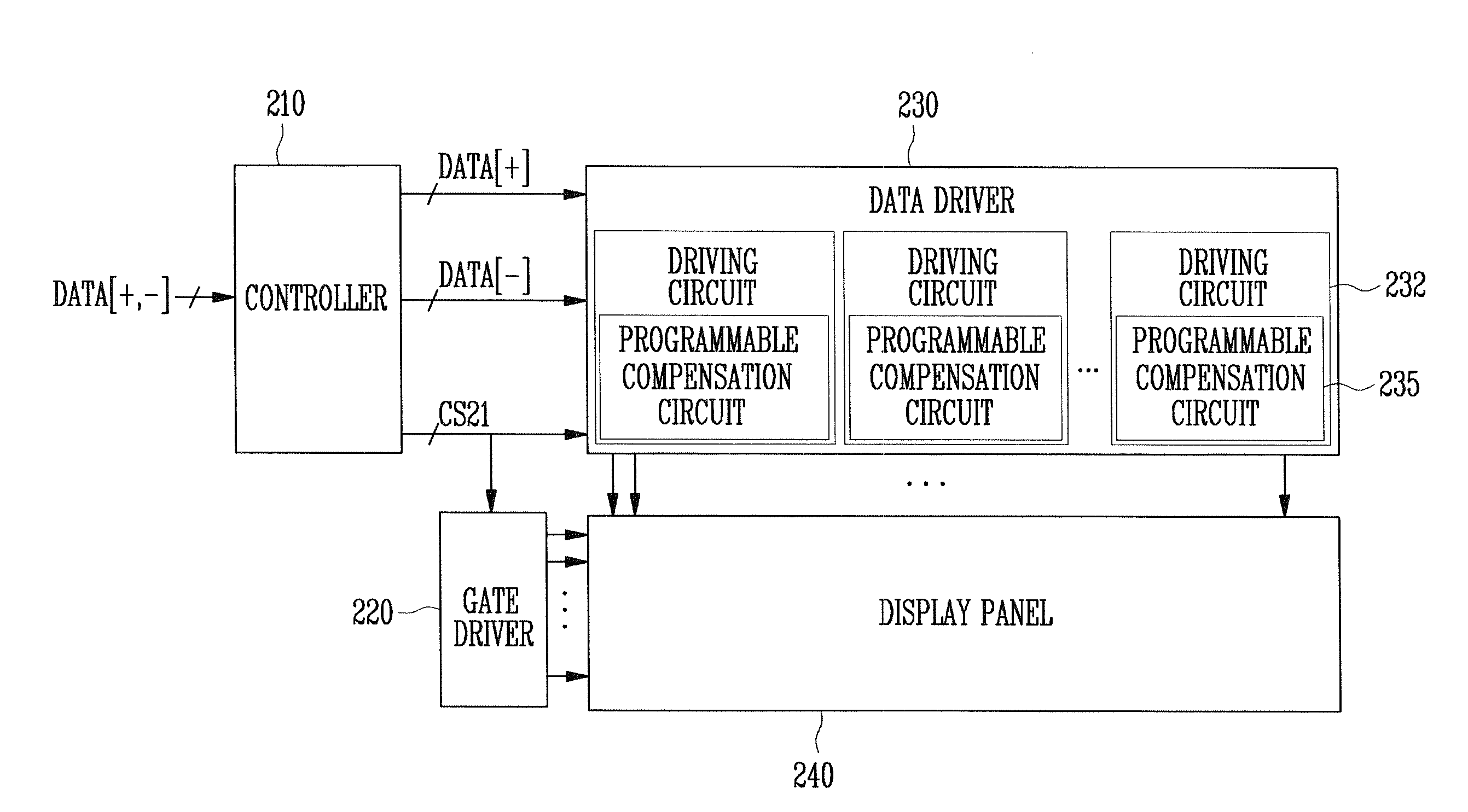
[0037]FIG. 4 is a block diagram showing the structure of a flat panel display according to an example embodiment of the present invention. As shown in FIG. 4, the flat panel display according to this example embodiment of the present invention includes a display panel 240, a gate driver 220, a data driver 230, and a controller 210. Gate wires and data wires are arranged to intersect ea...


PUM


Abstract

A differential signaling system where a first wire and a second wire are connected to a sending end and a receiving end of a differential signal line. A termination resistor is connected between the first wire and the second wire adjacent to the receiving end. A programmable compensation circuit is connected to the termination resistor in parallel. The programmable compensation circuit includes: a plurality of switches for receiving each bit of an input digital control signal through a gate thereof; a plurality of first capacitors including a first electrode connected to a source electrode of each of the switches, and a second electrode connected to the first wire; and a plurality of second capacitors including a first electrode connected to a drain electrode of each of the switches, and a second electrode connected to the second wire.

Description

CROSS-REFERENCE TO RELATED APPLICATION[0001]This application claims the benefit of Korean Application No. 2007-3361, filed Jan. 11, 2007 in the Korean Intellectual Property Office, the disclosure of which is incorporated herein by reference.BACKGROUND OF THE INVENTION[0002]1. Field of the Invention[0003]Aspects of the present invention relate to a flat panel display using a signal transmission method for transmitting a differential signal, and more particularly, to a flat panel display incorporating a differential signaling system for impedance matching in the signal transmission method.[0004]2. Description of the Related Art[0005]In general, a cathode ray tube (CRT) is one type of display device that has been widely used. CRTs have been used as monitors for television sets, measuring instruments, or information terminals. Because a CRT is heavy and large, it cannot be used when miniaturization or light weight are design requirements.[0006]Accordingly, in order to substitute for a C...

Claims


Application Information

Patent Timeline
Patent Type & Authority Applications(United States)
IPC IPC(8): G06F3/038H04L25/03
CPCG09G3/3688G09G2310/0275H04L25/0278H04L25/0272G09G2330/06H04B3/50G09G3/20
Inventor RYU, JEE-YOUL
Owner SAMSUNG DISPLAY CO LTD
Why Eureka
Try Eureka