Ink jet recording apparatus

a recording apparatus and jet recording technology, applied in printing and other directions, can solve the problems of large pressure loss, inability to perform normal image recording, and inability to record ink jets, and achieve the effect of efficient suction recovery action

Inactive Publication Date: 2008-09-04
CANON KK
View PDF22 Cites 17 Cited by
  • Summary
  • Abstract
  • Description
  • Claims
  • Application Information

AI Technical Summary

Benefits of technology

[0015]The present invention is directed to an ink jet recording apparatus capable of uniformizing suction force in a plurality of discharge ports to allow an efficient suction recovery action and to quickly eject, from a cap, ink suctioned from the discharge ports.

Problems solved by technology

In such a case, ink is no longer suitable for recording, and thus the ink jet recording apparatus may have trouble performing normal image recording.
However, in a conventional ink jet recording apparatus, the following problem remains to be solved.
Further, the ink absorber mounted in a cap is in the form of porous matrix, in which a large pressure loss may occur during discharge and suction of ink.
Accordingly, a tendency of an uneven pressure distribution inside the ink absorber causes a problem in which suction recovery in respective discharge ports cannot appropriately be performed.
Such an unbalanced suction force distribution occurs.
Therefore, it is difficult to control recovery processing of a recording head.
According to these tendencies, the ink jet recording apparatus is apt to cause such disadvantages that a pressure loss of the whole discharge ports of the recording head is increased and nonuniformity of suction force acting on respective discharge ports is increased.
Thus, the ink jet recording apparatus cannot efficiently suction ink from the discharge port.
This causes insufficient removal of a bubble or thickened ink in a discharge port, an increase in suction amount and suction time, a decrease in recording quality, and a decrease in performance of the ink jet recording apparatus itself.
However, these methods cause such disadvantages that an apparatus main body becomes complicated, an apparatus becomes large, a manufacturing cost increases, and recovery processing time becomes long.

Method used


Image

  • Ink jet recording apparatus
  • Ink jet recording apparatus
  • Ink jet recording apparatus

Examples


first exemplary embodiment

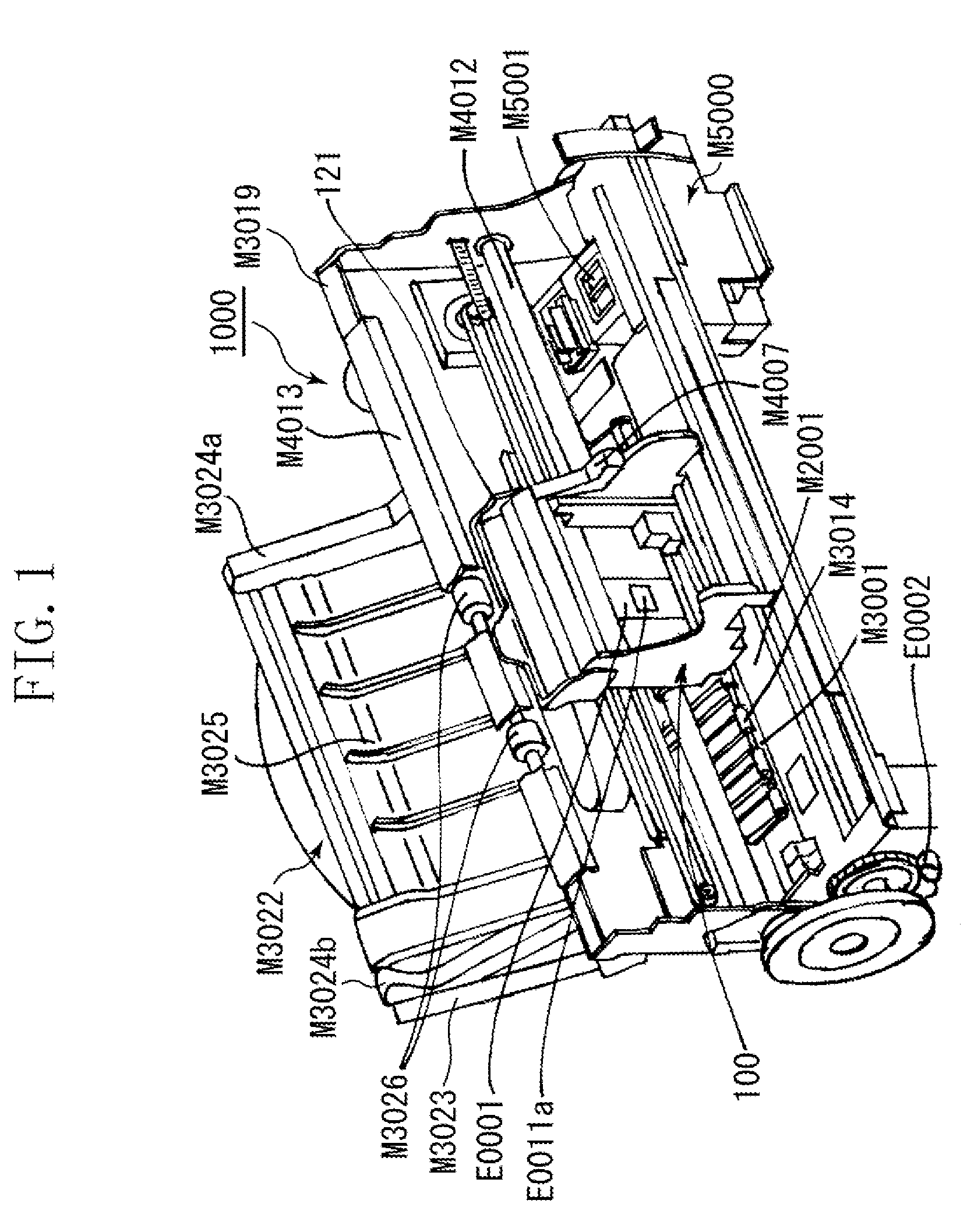
[0031]FIG. 1 is a perspective view illustrating an ink jet recording apparatus 1000 according to a first exemplary embodiment of the present invention. The ink jet recording apparatus 1000 is configured to discharge ink from a recording head to a recording material based on image information to record an image. The ink jet recording apparatus 1000 includes various mechanisms and various members for a recording action mounted on a chassis M3019 and an exterior member (not illustrated) covering their circumference. The mechanisms for a recording action include an automatic feed unit M3022, a conveying unit (not illustrated), an image forming unit (not illustrated), and a discharge recovery unit M5000. The automatic feed unit M3022 separates a sheet-like recording material, such as a recording sheet or a plastic sheet, one by one to feed the recording material toward the image forming unit inside the ink jet recording apparatus 1000. The conveying unit conveys a fed recording material ...

second exemplary embodiment

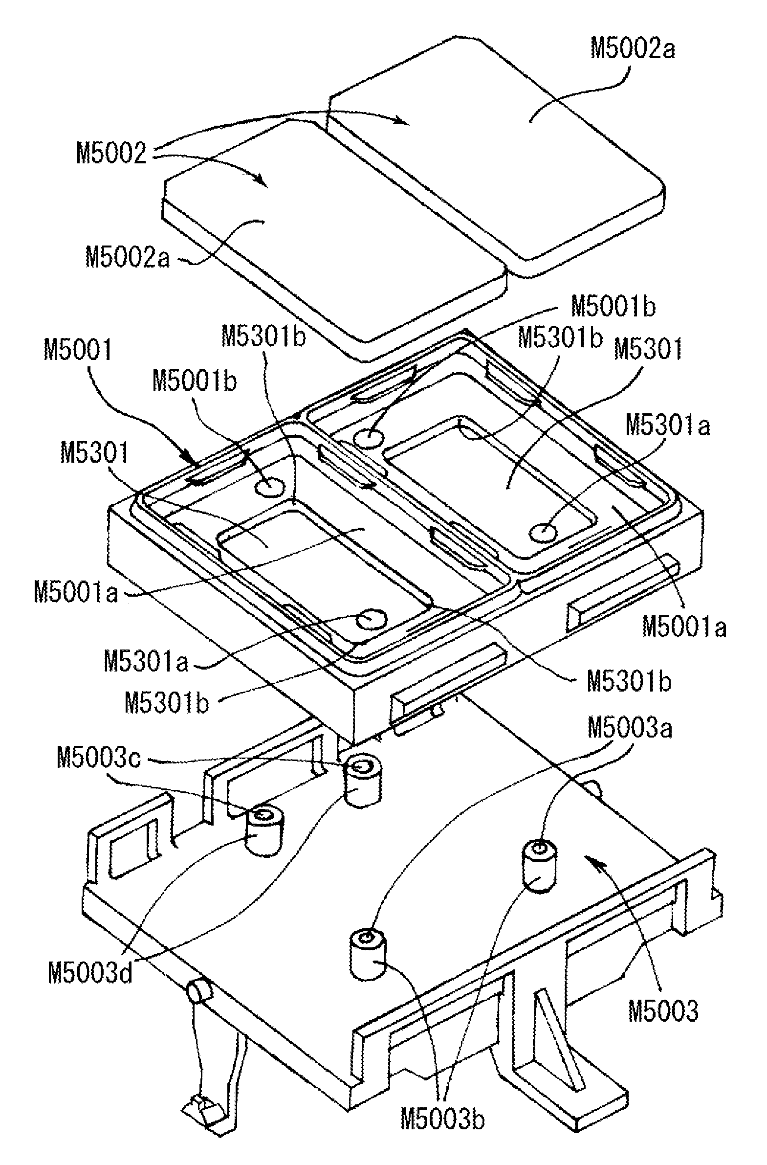
[0058]FIG. 9 is a perspective view illustrating a carriage unit according to a second exemplary embodiment of the present invention. FIG. 10 is an exploded perspective view illustrating a cap unit according to the second exemplary embodiment. FIG. 11 is a plan view illustrating a state of a discharge port of a recording head projected onto the bottom face inside a cap in an ink jet recording apparatus according to the second exemplary embodiment. In the second exemplary embodiment, a recording head 310 includes a plurality of recording element substrates 311 and 312 having different sizes. The recording head 310 can be capped with one cap M6001, in which one suction hole M6003a is located.

[0059]In FIGS. 9 to 11, a recessed portion M6301 is formed on a bottom face M6001a of the cap M6001. The suction hole M6003a is located in the recessed portion M6301. The cap M6001 is held by a cap holder M6003. The recessed portion M6301 includes a vertically long area M6303 and short area M6304, ...


PUM


Abstract

An ink jet recording apparatus configured to perform recording by discharging ink from a plurality of discharge ports disposed on a recording head. The apparatus includes a cap adapted to cover the plurality of discharge ports disposed on the recording head, a recessed portion defined on a bottom face inside the cap, a suction hole facilitating introducing a negative pressure to the recessed portion, an atmosphere communication hole located outside a range of the recessed portion and communicating with atmosphere, an ink absorber mounted inside the cap to cover the recessed portion, and a suction pump connected to the suction hole and configured to generate a negative pressure. When the plurality of discharge ports is covered with the cap, a projection image obtained when the plurality of discharge ports is projected onto the bottom face exists within the range of the recessed portion.

Description

BACKGROUND OF THE INVENTION[0001]1. Field of the Invention[0002]The present invention relates to an ink jet recording apparatus including a recording head configured to discharge ink from a plurality of discharge ports disposed on the recording head to perform recording, and a suction mechanism configured to maintain and recover an ink discharge performance of the recording head.[0003]2. Description of the Related Art[0004]Generally, a recording apparatus having a recording function, such as a printer, a copying machine, a facsimile machine, a word processor, a mailing machine, or a quick printing machine, records an image (also including a character, a symbol, and the like) on a recording material with a recording head based on image information. The recording apparatus can be classified into an ink jet type, a thermal transfer type, a laser beam type, a heat sensitive type, and a wire dot-matrix type based on various recording methods. Among these types, an ink jet recording appar...

Claims


Application Information

Patent Timeline
Patent Type & Authority Applications(United States)
IPC IPC(8): B41J2/165
CPCB41J2/1652B41J2/16508B41J2/16532
Inventor YAMAGUCHI, YUKUOKOIZUMI, YUTAKAUMEYAMA, MIKIYA
Owner CANON KK
Why Eureka
Try Eureka