Switchgear Cabinet for Accommodating Electronic Plug-In Modules with a Heat Exchanger

a technology of electronic plug-in modules and switchgear cabinets, which is applied in the direction of substation/switching arrangement cooling/ventilation, electrical equipment, cooling/ventilation/heating modifications, etc., can solve the problems of inability to transfer heat to the surroundings of the switchgear cabinet, the door and/or side walls of the cabinets cannot be perforated, and the individual module waste heat cannot be carried off. , to achieve the effect of reducing the structural height of small fans

Inactive Publication Date: 2008-09-04
SCHROFF GMBH
View PDF48 Cites 36 Cited by
  • Summary
  • Abstract
  • Description
  • Claims
  • Application Information

AI Technical Summary

Benefits of technology

[0027]In another preferred embodiment of the inventive switchgear cabinet, several fans are arranged in the roof area of the switchgear cabinet. The fans are preferably evenly distributed over the base area of the interior. It is particularly preferred to use four or nine fans arranged in a rectangular or square configuration. The use of several small fans has the advantage that a sufficiently high air throughput is still realized if one of the fans fails, so that overheating of the electronic plug-in modules can be reliably prevented. In addition, the structural height of small fans is frequently reduced, such that the switchgear cabinet usually can also be easily retrofitted with such fans.

Problems solved by technology

The waste heat of the individual modules increases due to the escalating power of electronic components, as well as the continuously increasing clock frequencies and the utilization of high-speed processors on the plug-in modules.
Consequently, the waste heat being generated can no longer be carried off merely by perforating the doors and / or side walls of the cabinets, as well as their bottoms and roofs.
A transfer of heat to the surroundings of the switchgear cabinet is not possible in this case.
However, if the heat exchanger is arranged on a side wall, several switchgear cabinets can be arranged only, if at all, adjacent to one another to a limited extent.
The available installation space for the cabinets is not optimally utilized.
If an air / water heat exchanger is arranged on the roof of the cabinet, escaping water or drops of condensation water can lead to damage to the electronic plug-in modules.
The cooling unit consisting of the heat exchanger and the fan is very costly.
However, the air conduction within the switchgear cabinet is poor because part of the airflow is once again deflected toward the air inlet of the heat exchanger.
If servicing is required, it is difficult to replace the fan arranged in the interior because it is necessary to open the region containing the electronic modules, so that the electronic units must invariably be switched off.

Method used


Image

  • Switchgear Cabinet for Accommodating Electronic Plug-In Modules with a Heat Exchanger
  • Switchgear Cabinet for Accommodating Electronic Plug-In Modules with a Heat Exchanger
  • Switchgear Cabinet for Accommodating Electronic Plug-In Modules with a Heat Exchanger

Examples


Embodiment Construction

[0033]In the following description, like numbers refer to like elements.

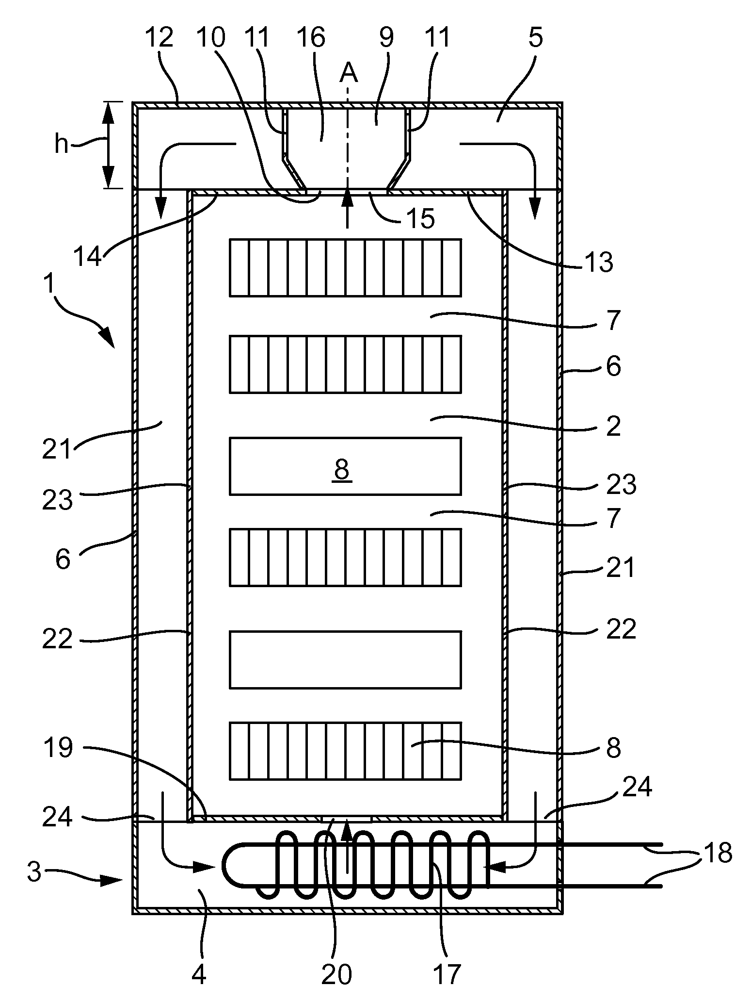
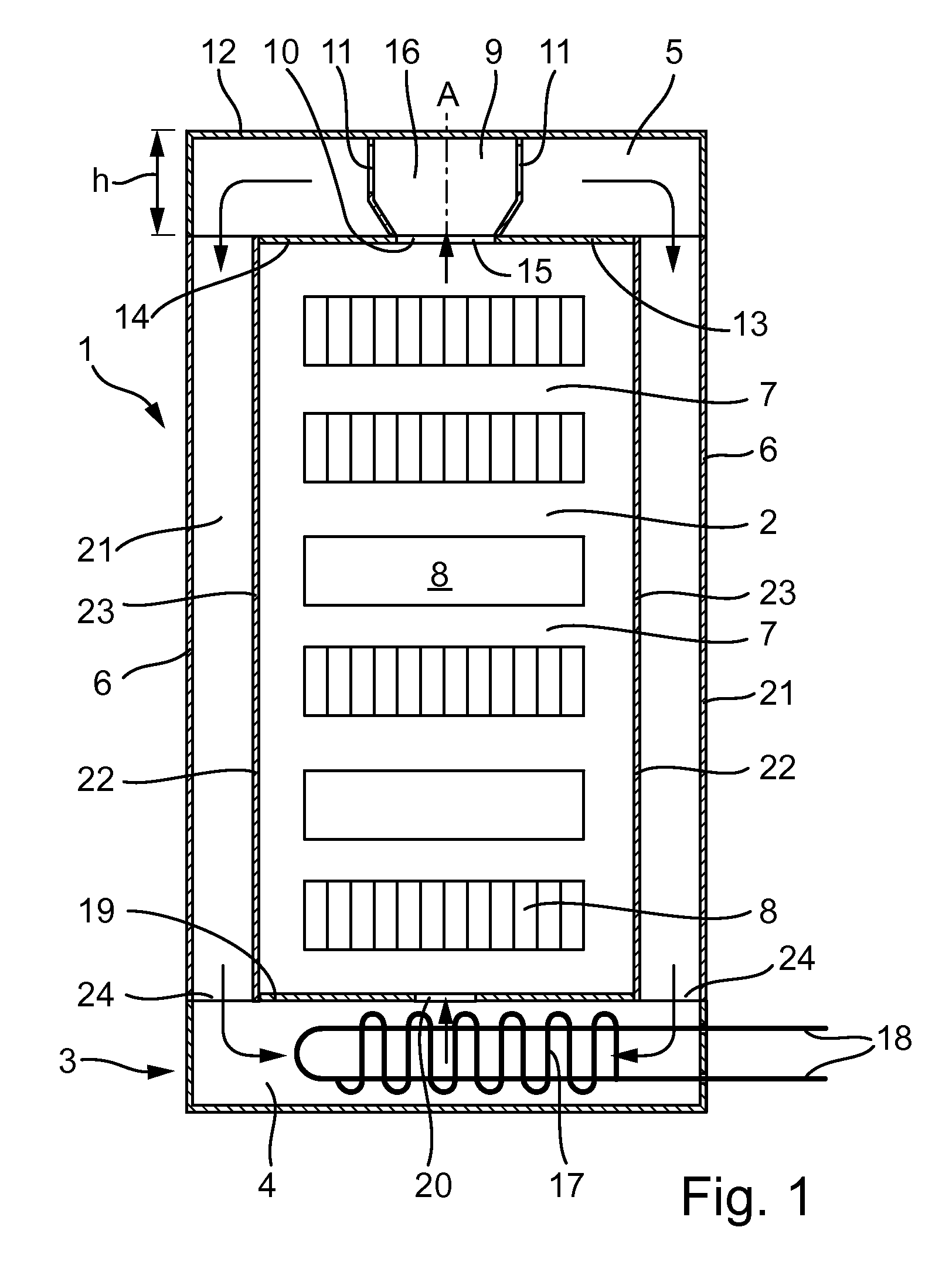
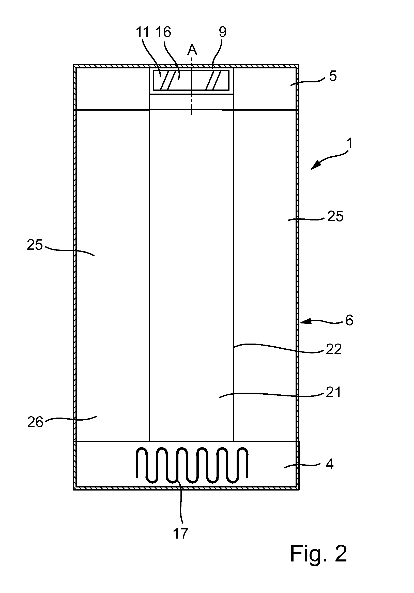
[0034]FIG. 1 shows a section through a switchgear cabinet 1 for accommodating electronic plug-in modules. The switchgear cabinet 1 comprises an interior 2, a base 3 arranged underneath the interior 2 and that forms a base area 4 and a roof area 5 arranged above the interior 2. Two vertically extending outer walls 6 form the periphery of the switchgear cabinet 1.

[0035]Plug-in modules 8 are arranged in the interior 2 in several planes 7 that are arranged one on top of another. The plug-in modules 8 of one plane 7 are separated from one another in such a way that air can vertically flow between the modules. On their front side, the plug-in modules 8 respectively feature front plates that end flush with one another. The plug-in modules 8 are displaceably supported in the individual planes 7 in horizontally extending guide rails.

[0036]The roof area 5 above the interior 2 contains a fan 9 that takes in air from the in...


PUM


Abstract

The present invention pertains to a switchgear cabinet for accommodating electronic plug-in modules with an interior in which the heat-generating plug-in modules can be inserted one on top of another, a roof area arranged above the interior and a base arranged underneath the interior and that forms a base area. The switchgear cabinet furthermore comprises an air channel that is arranged to the side of the interior and connects the roof area to the base area. A closed cooling circuit within the switchgear cabinet serves for carrying off the heat generated by the plug-in modules. A fan arranged in the roof area takes in air from the interior and blows this air into the air channel. The heated air from the air channel flows around a heat exchanger arranged in the base in such a way that the air is cooled and the thereby produced cooling air is admitted into the interior from below and flows through this interior vertically upwards.

Description

TECHNICAL FIELD OF THE INVENTION[0001]The present invention pertains to a switchgear cabinet for accommodating electronic plug-in modules with a heat exchanger.BACKGROUND[0002]Switchgear cabinets are typically fitted with a series of plug-in modules that are arranged one on top of another in several layers. The plug-in modules are inserted into guide rails provided for this purpose and aligned vertically. The adjacent plug-in modules are separated from one another in such a way that the heat generated by the modules can be transferred to their surroundings. The transferred heat is carried off by the air circulating between the modules.[0003]The waste heat of the individual modules increases due to the escalating power of electronic components, as well as the continuously increasing clock frequencies and the utilization of high-speed processors on the plug-in modules. Consequently, the waste heat being generated can no longer be carried off merely by perforating the doors and / or side...

Claims


Application Information

Patent Timeline
Patent Type & Authority Applications(United States)
IPC IPC(8): H05K7/20
CPCH05K7/20754
Inventor MAZURA, PAULPAWLOWSKI, ADAM
Owner SCHROFF GMBH
Why Eureka
Try Eureka