Steam Turbine

Inactive Publication Date: 2008-09-04
ALSTOM TECH LTD
View PDF7 Cites 13 Cited by
  • Summary
  • Abstract
  • Description
  • Claims
  • Application Information

AI Technical Summary

Benefits of technology

[0010]One of numerous aspects of the invention, therefore, includes creating a steam turbine which addresses the disadvantages of known steam turbines and which, in particular, includes an inner casing which can be more easily and more cost-effectively produced.
[0011]According to another, particularly advantageous aspect of the invention, the inner casing is formed as a welded construction, in which the blade carriers, for fastening the stator blades, which blade carriers delimit the steam passages and are produced as castings, are supported by additional forged or rolled steel elements. Since the cast parts with this solution are limited to the blade carriers and, therefore, are formed in a smaller and less complicated manner, fewer fabrication and repair problems result. At the same time, radial and axial deformations of the blade carriers are less than with an integrated cast casing, so that narrower gaps at the blade tips, and therefore higher efficiency of the turbine, are possible.

Problems solved by technology

With this solution, it is disadvantageous that such casings are very difficult to produce.
The number of manufacturers, therefore, is limited and problems frequently occur.
Also, it is difficult to repair such castings if problems occur during casting or during the subsequent machining.

Method used


Image

  • Steam Turbine
  • Steam Turbine
  • Steam Turbine

Examples


Embodiment Construction

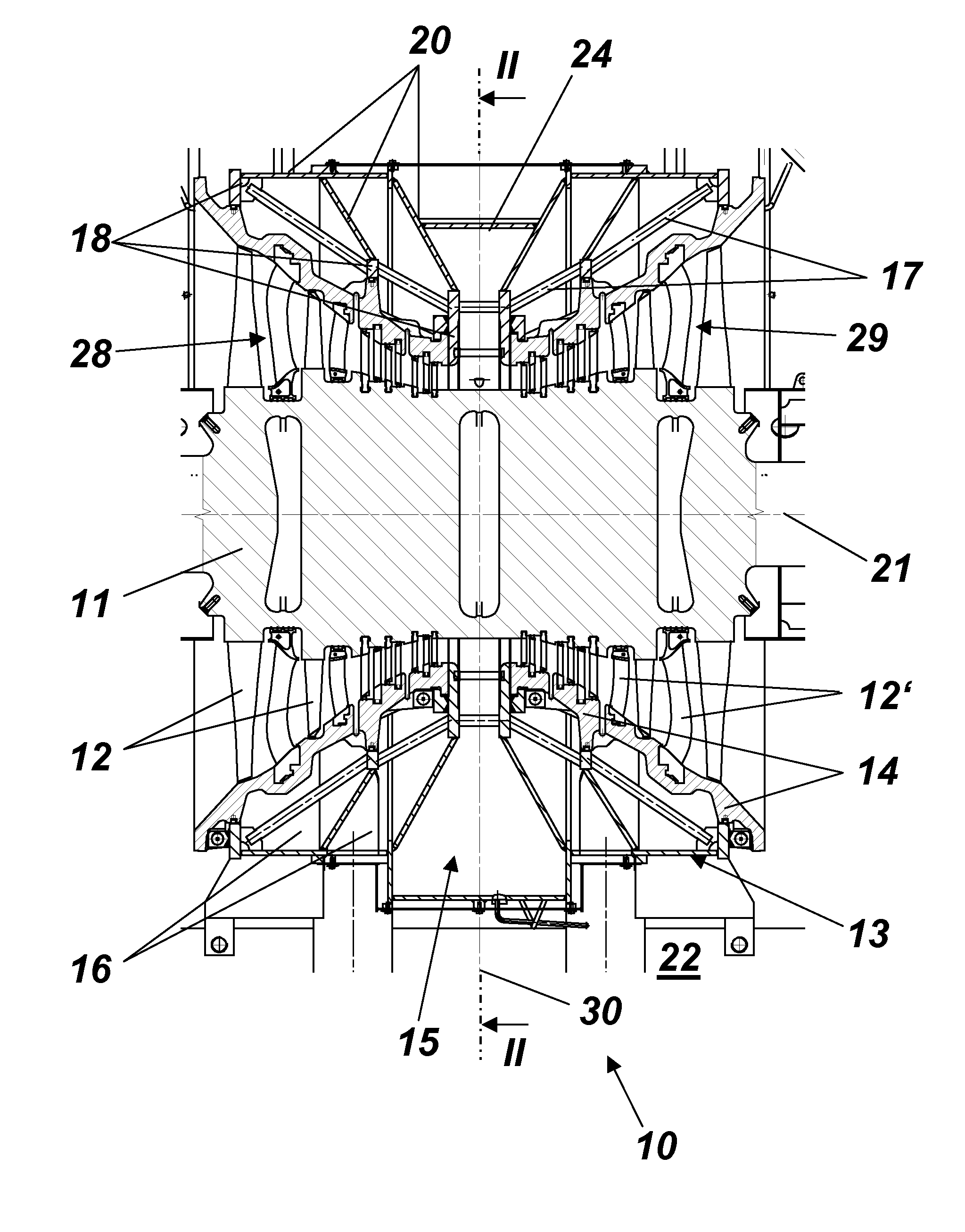
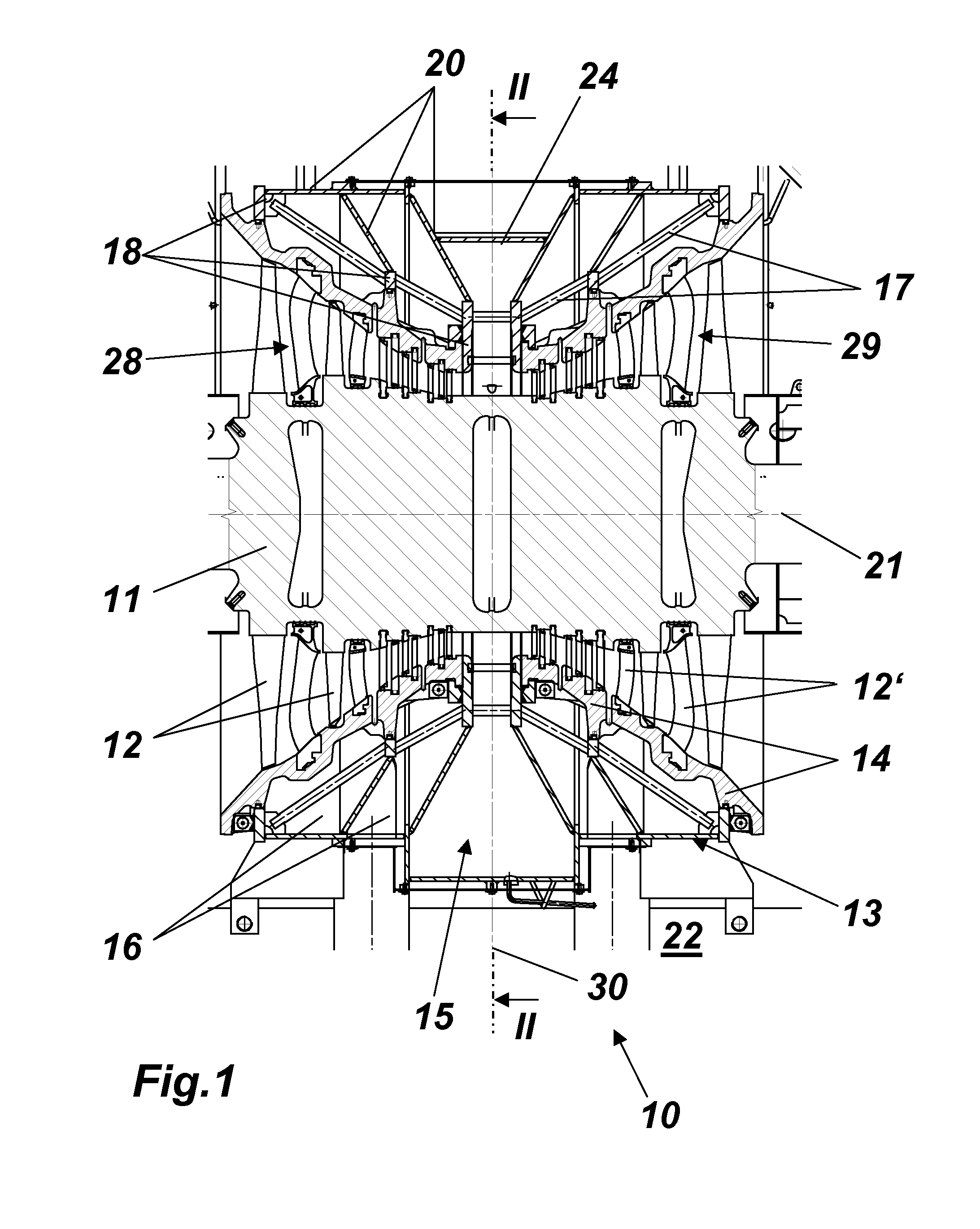
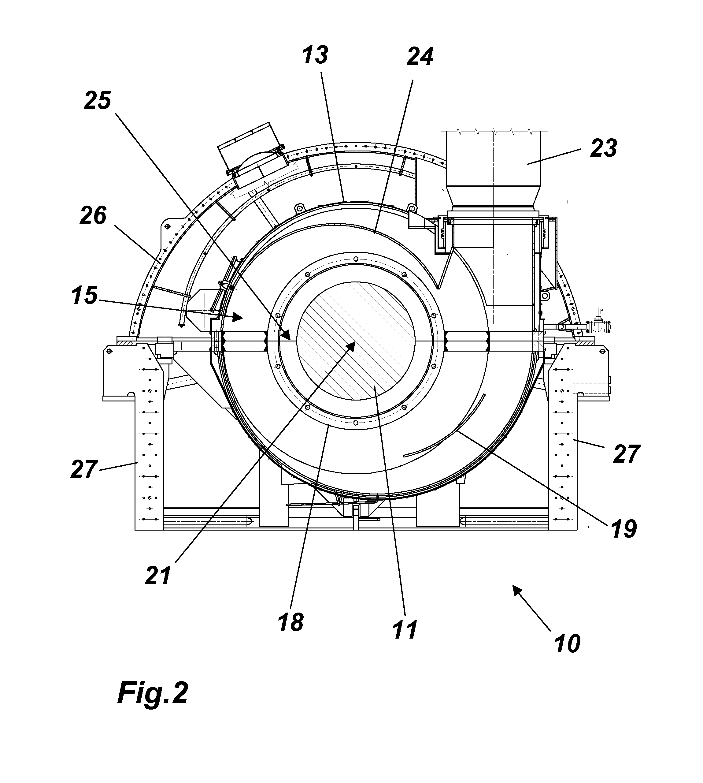
[0021]In FIG. 1, a double-flow low-pressure steam turbine, with its inner casing according to an exemplary embodiment of the invention, is represented in longitudinal section. FIG. 2 shows the section of this turbine in the center plane (plane II-II in FIG. 1). The steam turbine 10 is constructed with its two flows mirror-symmetrical to a vertical center plane 30. It includes a rotor 11, which is rotatable around a horizontal axis 21 and concentrically enclosed with a spacing by an inner casing 13. Outwards widening annular steam passages 28, 29 are formed between the rotor and the inner boundary wall of the inner casing, through which the steam, which is fed radially in the center, flows outwards and, expanding on the rotor blades 12 which are fastened on the rotor 11, performs work.

[0022]Rows of fixed stator blades 12′, which are fastened on blade carriers 14 on the root side, alternate with the rows of rotor blades 12. The blade carriers 14 are cast parts and preferably are forme...


PUM


Abstract

A steam turbine (10), especially in the form of a double-flow low-pressure steam turbine, includes a rotor (11) which is rotatably mounted around an axis (21) and which is concentrically enclosed with a spacing by an inner casing (13), forming annular steam passages (28, 29), and which has a multiplicity of rotor blades (12) which project into the steam passages (28, 29), wherein the inner casing (13) supports a multiplicity of stator blades (12) which project into the steam passages (28, 29) and which, for feeding steam to the steam passages (28, 29), has an inlet duct (15) which is directed around the axis (21) and tapers in the flow cross section. With such a steam turbine, the production is simplified by the inner casing (13) being formed as a welded construction, in which blade carriers (14), which delimit the steam passages (28, 29) and are produced as cast parts, are welded to additional forged or rolled steel elements (20) for fastening the stator blades (12′).

Description

[0001]This application claims priority under 35 U.S.C. § 119 to Swiss application No. 00349 / 07, filed 2 Mar. 2007, the entirety of which is incorporated by reference herein.BACKGROUND OF THE INVENTION[0002]1. Field of the Invention[0003]The present invention relates to the field of thermal machines, and more particularly to a steam turbine.[0004]2. Brief Description of the Related Art[0005]With large steam turbosets, as are described, for example, in the article by L. Busse et al., “World's highest capacity steam turbosets for the lignite-fired Lippendorf power station”, ABB review 6 / 1997, p. 13-22 (1997), and are shown in FIG. 2 there, double-flow low-pressure steam turbines are used, in which the steam is fed radially via a central scroll-shaped inlet duct, and then flows out in both directions through the steam passages which are formed between the rotor and the concentric inner casing, and, expanding on the rotor blades of the rotor, performs work. The inlet scroll is integrated...

Claims


Application Information

Patent Timeline
IPC IPC(8): F01D9/00F01D25/24
CPCF01D25/26F01D25/28F05B2260/301F05D2240/14F05D2220/31F05D2230/21F05D2230/232F05D2230/235
Inventor LAGEDER, HEINRICHLUKASIK, LUCJANGREIM, RALFSCHREIER, THOMASFISCHER, MICHAEL
Owner ALSTOM TECH LTD
Why Eureka
Try Eureka