Method of manufacturing a magnetic recording head

a manufacturing method and magnetic recording technology, applied in the field of manufacturing a magnetic recording head, can solve the problems of unstable angle of both side surfaces, unstable core width of the front tip, and instability of the main magnetic pole after trimming, and achieve the effect of stable recording performance, small fluctuation, and small fluctuation

Inactive Publication Date: 2008-09-04
FUJITSU LTD
View PDF7 Cites 3 Cited by
  • Summary
  • Abstract
  • Description
  • Claims
  • Application Information

AI Technical Summary

Benefits of technology

[0032]By doing so, the surfaces of the resist layer can be favorably hardened.
[0033]According to the method of manufacturing a magnetic recording head according to the present invention, by making it possible to form the main magnetic pole with no deformation, it is possible to form the front tip of the main magnetic pole with little fluctuation in the core width and angles of both side surfaces and to form the main magnetic pole with little fluctuation in the neck height. Accordingly a magnetic recording head with stable recording performance can be manufactured.

Problems solved by technology

Since a trimming process is carried out on the main magnetic pole as described above, there is the problem that the core width of the front tip 10a of the main magnetic pole and the angle of both side surfaces after trimming become unstable (i.e., fluctuate).
Also, as shown in FIG. 7 (where the main magnetic pole is viewed from above in the laminating direction), a neck portion 10d that is the boundary between the front tip 10a and the yoke portion 10c of the main magnetic pole 10 also deforms to become rounded and there is fluctuation in the neck height of the main magnetic pole (i.e., the length of the front tip 10a, or in other words, the distance from the neck portion 10d to the air bearing surface), resulting in instability in the recording performance.

Method used


Image

  • Method of manufacturing a magnetic recording head
  • Method of manufacturing a magnetic recording head
  • Method of manufacturing a magnetic recording head

Examples


specific examples

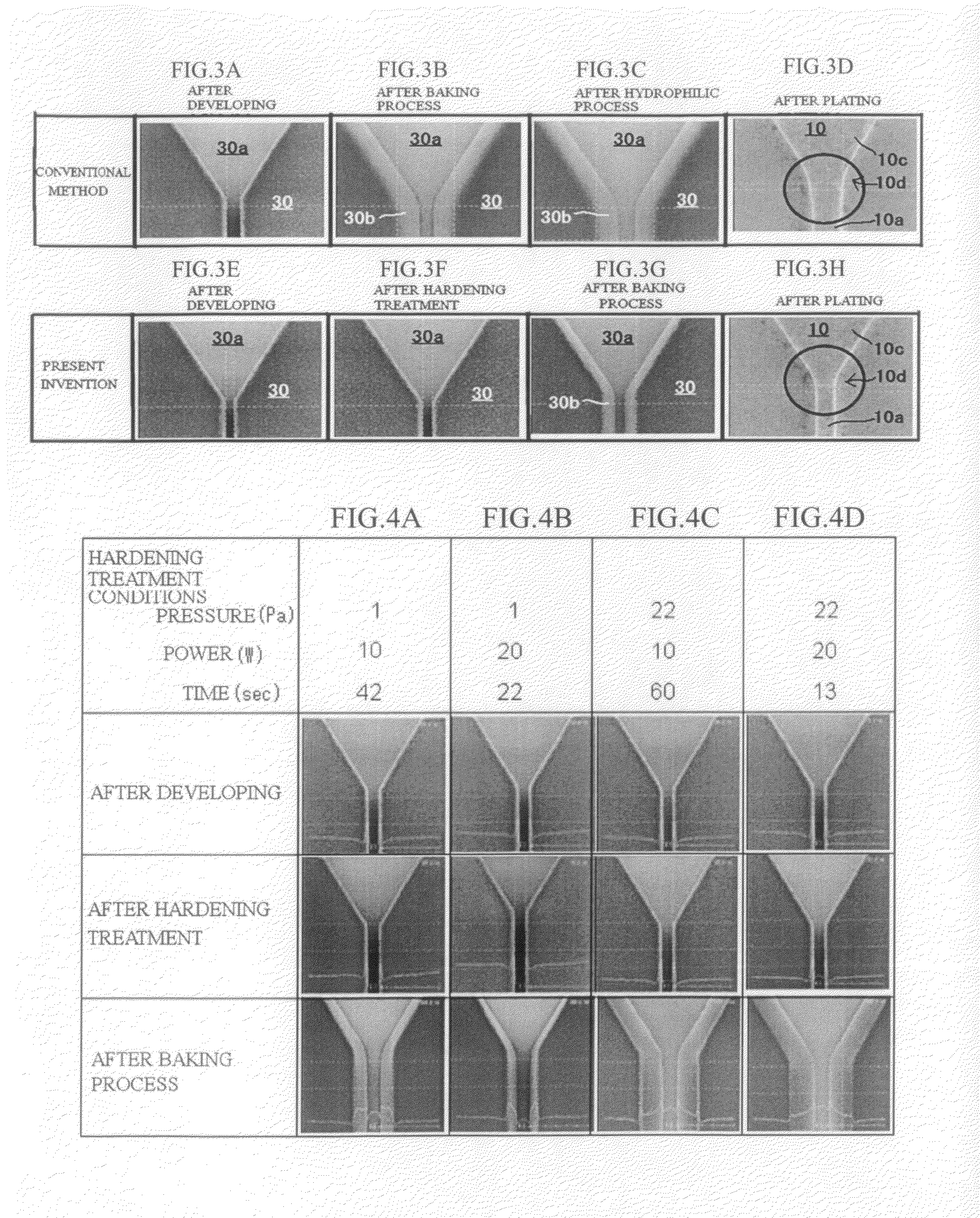
[0077]FIGS. 4A to 4D are SEM images of a resist layer for which processes as far as the baking process have been carried out with different plasma irradiation conditions during the hardening treatment.

[0078]FIG. 4A shows the case where the O2 gas pressure was set at 1 Pascal, the bias power at 10 W, and the plasma irradiation time at 42 seconds. In the same way, FIG. 4B shows the case where the O2 gas pressure was set at 1 Pascal, the bias power at 20 W, and the plasma irradiation time at 22 seconds. FIG. 4C shows the case where the O2 gas pressure was set at 22 Pascals, the bias power at 10 W, and the plasma irradiation time at 60 seconds. FIG. 4D shows the case where the O2 gas pressure was set at 22 Pascals, the bias power at 20 W, and the plasma irradiation time at 13 seconds.

[0079]Note that in each case, the heating temperature during the baking process was set at 157° C. and the processing temperature was set at 180 seconds.

[0080]Also in each case, a chemically-amplified posit...


PUM

PropertyMeasurementUnit
pressureaaaaaaaaaa
bias poweraaaaaaaaaa
temperatureaaaaaaaaaa

Abstract

A method of manufacturing a magnetic recording head includes a resist pattern forming step of forming a resist layer that is made of thermoplastic resin and in which a hole is formed in the shape of a main magnetic pole of the magnetic recording head, a hardening treatment step of hardening surfaces of the resist layer; a baking step that heat-bakes the resist layer after the hardening treatment step to temporarily make the resist layer fluid; and a main magnetic pole forming step of forming a main magnetic pole by filling the hole in the resist layer with a material of the main magnetic pole.

Description

BACKGROUND OF THE INVENTION[0001]1. Field of the Invention[0002]The present invention relates to a method of manufacturing a magnetic recording head that forms a main magnetic pole of the magnetic recording head by forming a resist layer that is made of thermoplastic resin and in which a hole in the shape of the main magnetic pole is formed, heat-baking the resist layer to temporarily make the layer fluid, and then filling the hole in the resist layer with the material that composes the main magnetic pole.[0003]2. Related Art[0004]Patent Document 1 discloses a conventional method of manufacturing a magnetic recording head. The steps in the conventional method of manufacturing a magnetic recording head for perpendicular magnetic recording disclosed in Patent Document 1 are schematically shown in FIGS. 5A to 5F. FIGS. 5A to 5F are cross-sectional views of the periphery of a front tip of a main magnetic pole of a magnetic recording head during manufacturing when looking from the air be...

Claims


Application Information

Patent Timeline
Patent Type & Authority Applications(United States)
IPC IPC(8): C08J7/18
CPCG11B5/3163G11B5/1278G11B5/127
Inventor INUKAI, KAZUAKIKON, JUNICHI
Owner FUJITSU LTD
Why Eureka
Try Eureka