Replacement prosthetic heart valves and methods of implantation

a prosthetic heart valve and implanting method technology, applied in the field of prosthetic heart valves, can solve the problem that the deficient prosthetic heart valve cannot be physically removed from the patient, and achieve the effect of avoiding the need for physical removal

Inactive Publication Date: 2008-09-04
MEDTRONIC INC
View PDF99 Cites 227 Cited by
  • Summary
  • Abstract
  • Description
  • Claims
  • Application Information

AI Technical Summary

Benefits of technology

[0013]Insertion or implantation of the replacement heart valves of the invention can be accomplished using delivery systems that can maintain the stent structures in their compressed state during their insertion and allow or cause all or specific features of the stent structures to expand once they are in their desired location. In addition, some stents of the invention can further include features that a

Problems solved by technology

Further, in cases where a previously implanted prosthetic heart valve is being functionally r

Method used


Image

  • Replacement prosthetic heart valves and methods of implantation
  • Replacement prosthetic heart valves and methods of implantation
  • Replacement prosthetic heart valves and methods of implantation

Examples


Embodiment Construction

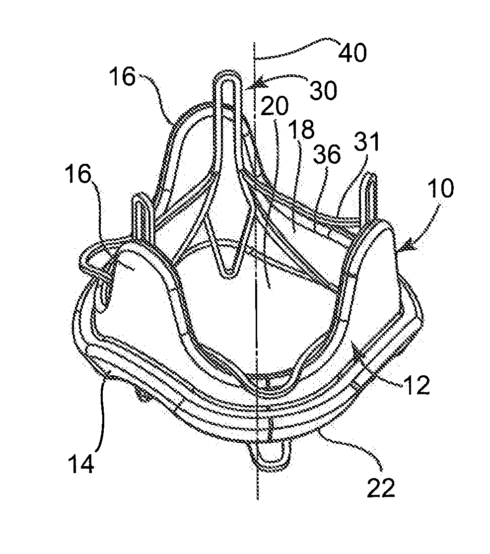
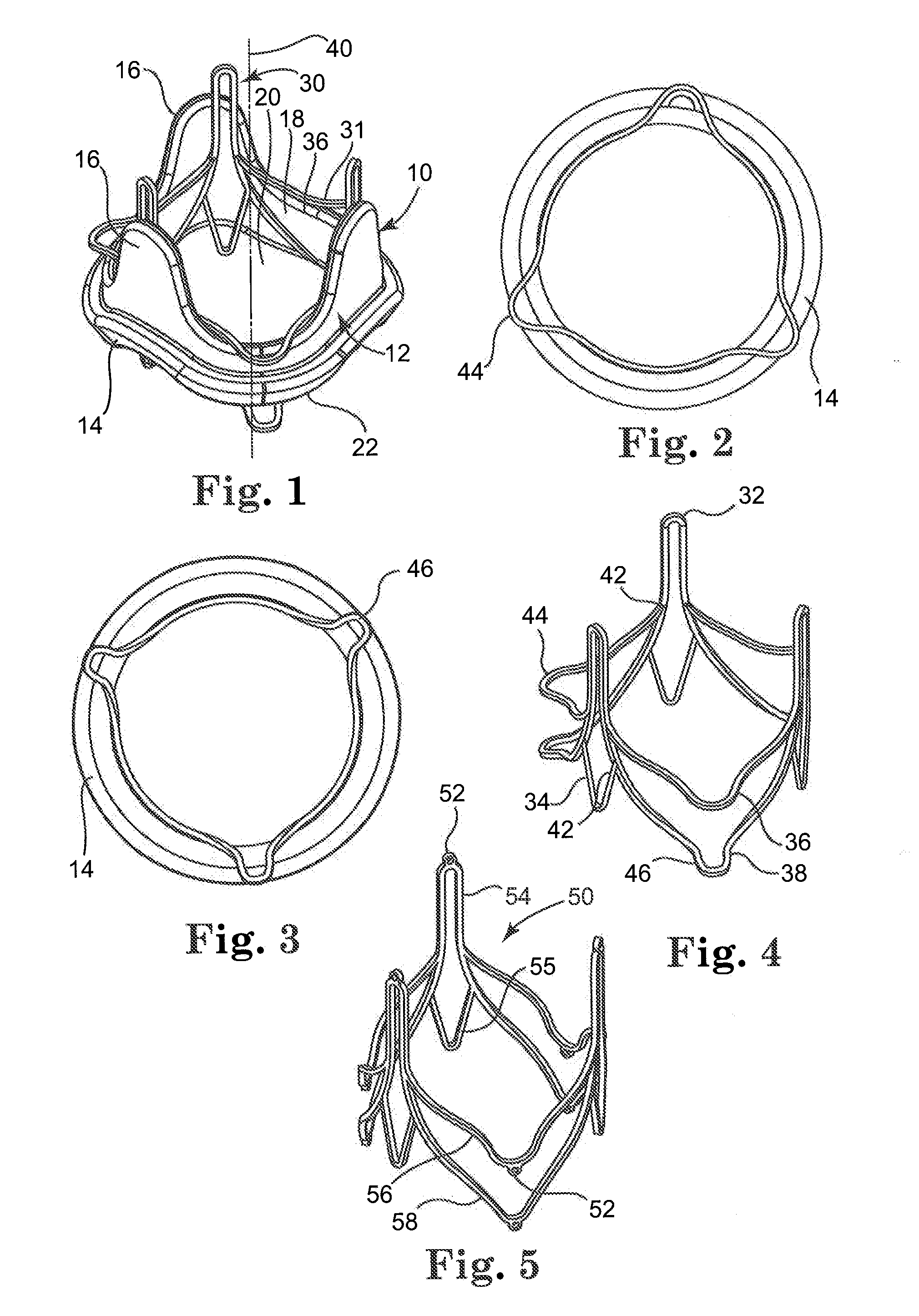
[0063]Referring now to the Figures, wherein the components are labeled with like numerals throughout the several Figures, and initially to FIG. 1, a prosthetic heart valve 10 is illustrated with a stent 30 of the invention positioned therein, which will be described in further detail below. However, referring specifically to the prosthetic heart valve 10, this valve 10 is a typical configuration of a valve that can be implanted within the heart of a patient, such as by suturing or otherwise securing the valve 10 into the area of a native heart valve of a patient. The native heart valves referred to herein can be any of the human heart valves (i.e., mitral valve, tricuspid valve, aortic valve, or pulmonary valve), wherein the type and orientation of an implanted (e.g., surgically implanted) prosthetic heart valve 10 will correspond with the particular form, shape, and function of the native heart valve in which it is implanted. Although valve 10 would typically include multiple leafl...


PUM


Abstract

A replacement prosthetic heart valve for engagement with a structure of a previously implanted prosthetic heart valve, the replacement heart valve including a stent structure and at least two leaflets attached within the interior area of a tubular body portion of the stent structure. The stent structure includes a generally tubular body portion having an interior area, at least two upper flange portions for positioning at an outflow end of the previously implanted heart valve, wherein the upper flange portions extend radially outward from the tubular body portion and are biased toward an inflow end of the replacement heart valve, and at least one lower flange portion for positioning at an inflow end of the previously implanted heart valve, wherein the lower flange portions extend radially outward from the tubular body portion and are biased toward an outflow end of the replacement heart valve.

Description

CROSS-REFERENCE TO RELATED APPLICATION [0001]The present application claims priority to U.S. Provisional Application No. 60 / 901,787, filed Feb. 16, 2007, and titled “Replacement Prosthetic Heart Valve Including Delivery System and Method of Implantation”, the entire contents of which is incorporated herein by reference in its entirety.TECHNICAL FIELD [0002]The present invention relates to prosthetic heart valves. More particularly, it relates to devices, methods, and delivery systems for percutaneously implanting prosthetic heart valves.BACKGROUND [0003]Various types and configurations of prosthetic heart valves are used to replace diseased natural human heart valves. The actual shape and configuration of any particular prosthetic heart valve is dependent to some extent upon the valve being replaced (i.e., mitral valve, tricuspid valve, aortic valve, or pulmonary valve). In general, the prosthetic heart valve designs attempt to replicate the function of the valve being replaced and ...

Claims


Application Information

Patent Timeline
IPC IPC(8): A61F2/24
CPCA61F2/2418A61F2/2433A61F2230/0054A61F2/2436A61F2220/005A61F2/958A61F2210/0014A61F2220/0075A61F2230/0069A61F2310/00023A61F2/2409
Inventor RYAN, TIMOTHY R.MORROW, JOSEPH C.
Owner MEDTRONIC INC
Why Eureka
Try Eureka