Footwear for the Diet Equipped with the Buffering Means
a technology for diet footwear and buffering means, applied in the field of health and diet footwear with buffering means, can solve the problems of tunnel type fixing members b>7/b> being abraded or even damaged, and the entire footwear should be useless, so as to prevent the generation of noise, save costs, and avoid the effect of generating nois
- Summary
- Abstract
- Description
- Claims
- Application Information
AI Technical Summary
Benefits of technology
Problems solved by technology
Method used
Image
Examples
first embodiment
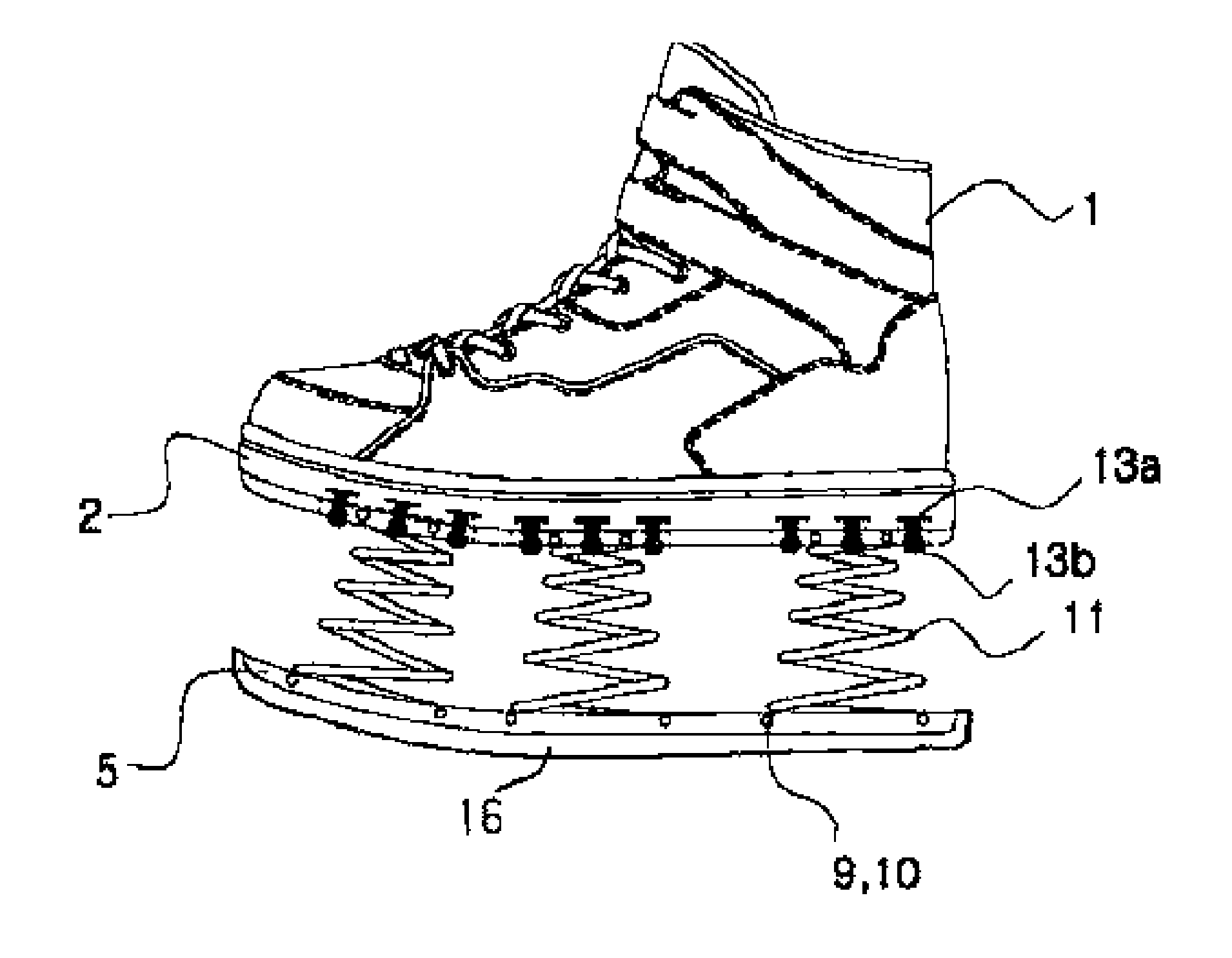
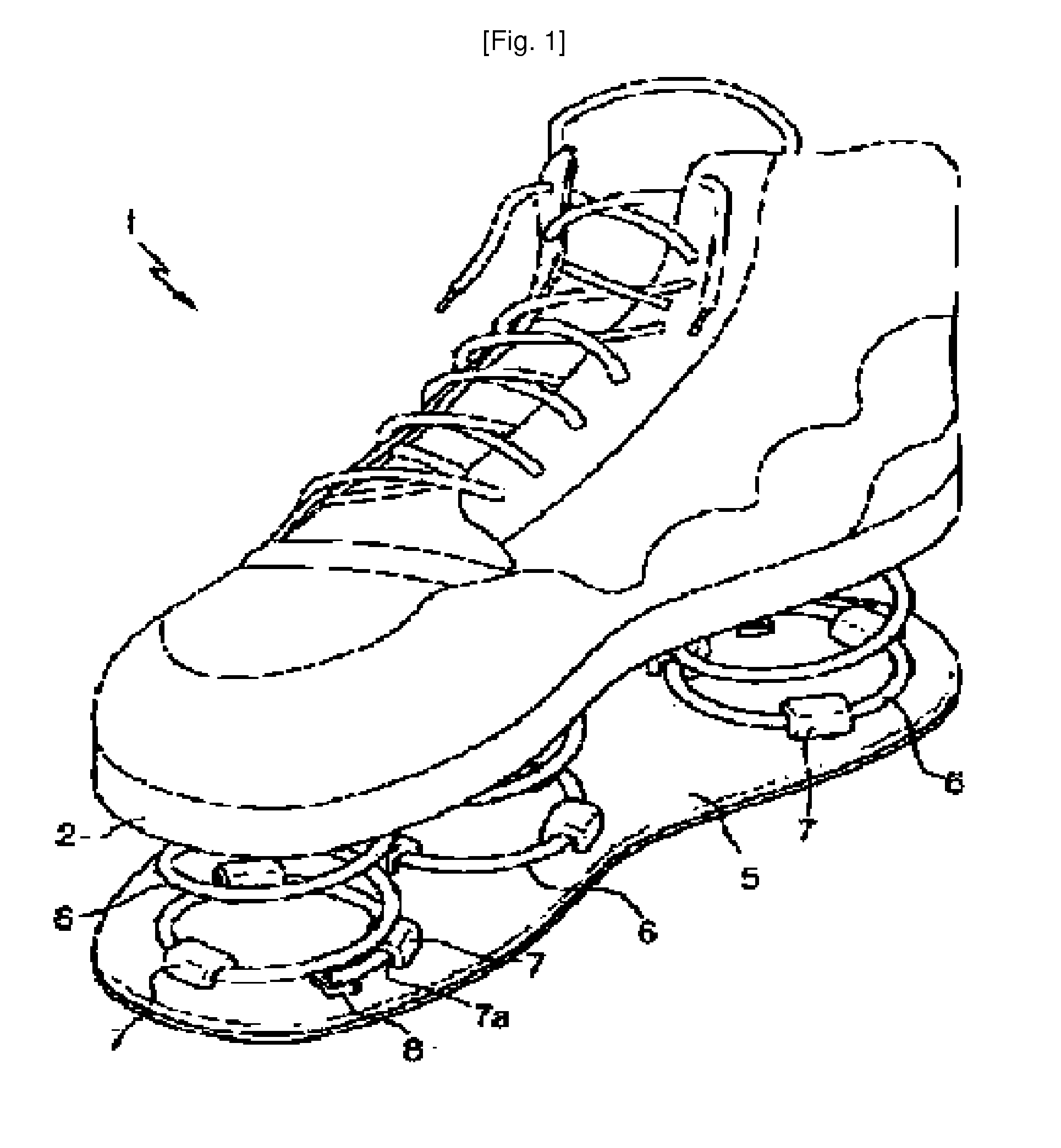
[0020]The coupling structure of the spring member 11 is very important in the health and diet footwear 1, and according to the teachings of the present invention, the spring members 11 can be detachably mounted individually in rigid and easy manners. In more detail, a plurality of spring members 11 are erected and coupled between the sole 2 and the support plate 5, as mentioned in the prior art, for elastically supporting a wearer's weight.
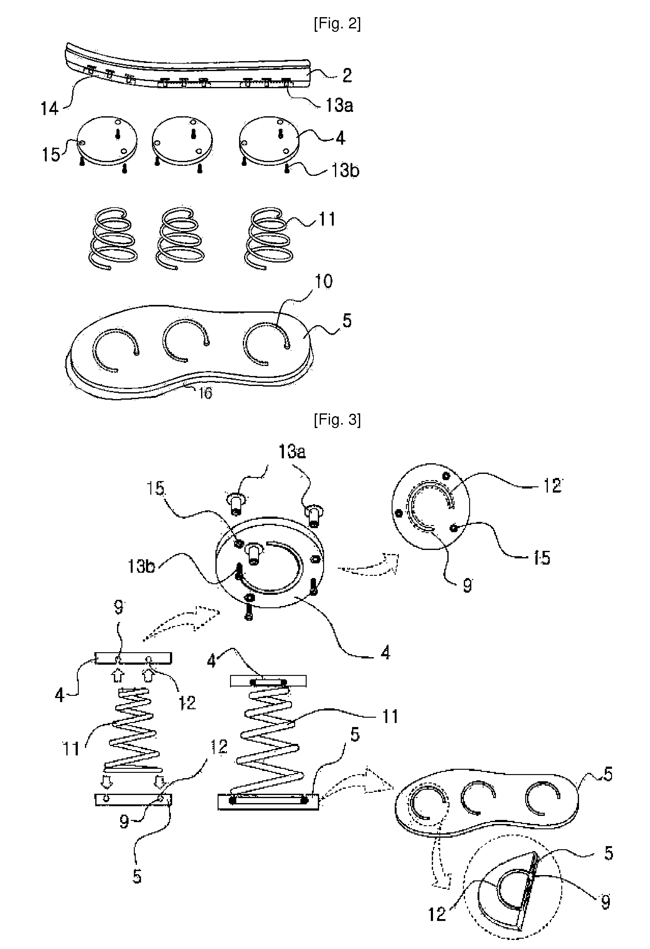
[0021]As mentioned above, the object of the present invention is to provide the coupling structure of the spring members wherein the spring members 11 can be detachably mounted individually in more rigid and easier manners as compared to the prior art spring footwear. Thus, an insertion groove 9 is formed with no protrusion on each of the fixed plates 4 to which the upper end portion of each of the spring members 11 is coupled and on the support plate 5 to which the lower end portion of each spring member 11 is coupled, having a size corresponding...
second embodiment
[0025]In addition to the coupling structure of the insertion groove 9 wherein the steel wire of the spring member 11 is detachably mounted as mentioned above, another embodiment of the present invention will be suggested herein. Also, the second embodiment of the present invention is aimed to solve the conventional problem that the protruded fixing members 7 are abraded and damaged, and according to the second embodiment of the present invention, a spiral tunnel hole 10 is formed inside the fixed plate 4 to which the upper end portion of each of the spring members 11 is coupled and on the support plate 5 to which the lower end portion of each of the spring members 11 is coupled.
[0026]In more detail, the spring member 11 is of a generally spiral shape such that the upper portions are spaced apart from the lower portions at given intervals. Thus, the spiral tunnel hole 10 is formed to a shape corresponding to the spiral spring member 11 on the fixed plate 4 and the support plate 5, an...
third embodiment
[0028]The present invention also proposes the coupling structure of the fixed plate 4 fixed to the sole 2, but in the conventional practice, the fixed plate 4 is fixed by means of the rivets 3 on the sole 2. Once fixed, thus, if a portion of the spring members 6 is damaged or broken while in use, it cannot be exchanged with new one.
[0029]According to the present invention, so as to solve this problem, the fixed plate 4 is fixed by means of a screw part 13 including female screws 13a and male screws 13b detachably mounted on the sole 2, and thus, if the spring member 11 is to be exchanged after damaged, the corresponding female and male screws 13a and 13b are unfastened and individually exchanged with new one.
[0030]First of all, referring in detail to the fixing structure of the fixed plate 4 to the sole 2, a plurality of fixed plate-attaching recesses 14 are formed on the bottom surface of the sole 2, each of the fixed plate-attaching recesses 14 has a diameter and a thickness corre...
PUM
 Abstract
Description
Claims
Application Information
 - R&D
- Intellectual Property
- Life Sciences
- Materials
- Tech Scout
- Unparalleled Data Quality
- Higher Quality Content
- 60% Fewer Hallucinations
Browse by: Latest US Patents, China's latest patents, Technical Efficacy Thesaurus, Application Domain, Technology Topic, Popular Technical Reports.
© 2025 PatSnap. All rights reserved.Legal|Privacy policy|Modern Slavery Act Transparency Statement|Sitemap|About US| Contact US: help@patsnap.com


