Sand control screen having a micro-perforated filtration layer

a technology of filtration layer and sand control screen, which is applied in the direction of drinking water installation, borehole/well accessories, construction, etc., can solve the problems of poor productivity, high maintenance cost, and erosion of tubing, and achieve the effect of simple manufacturing and easy cleaning

Inactive Publication Date: 2008-09-11
HALLIBURTON ENERGY SERVICES INC
View PDF34 Cites 60 Cited by
  • Summary
  • Abstract
  • Description
  • Claims
  • Application Information

AI Technical Summary

Benefits of technology

[0010]The present invention disclosed herein comprises a sand control screen having a micro-perforated filter layer for filtering particles out of fluid produced from a wellbore and a method for manufacturing the same. The sand screen of the present invention allows for precise, reliably reproducible and infinitely variable opening size, shape, density and pattern in the micro-perforated filter layer, thereby providing the desired sand control function. In addition, the sand control screen of the present invention is robust, easy to clean and simple to manufacture.

Problems solved by technology

Production of these materials causes numerous problems in the operation of oil, gas or water wells.
These problems include plugging of formations, tubing and flow lines, as well as erosion of tubing, downhole equipment and surface equipment.
These problems lead to poor productivity, high maintenance costs and unacceptable well downtime.
It has been found, however, that existing sand screens continue to have a number of drawbacks.
For example, variations in the gauge of the wire or improper manufacture can result in inconsistencies in the opening size.
Larger gauges of wire become increasingly difficult to bend, while smaller gauges are more easily damaged in the processes of manufacture and installation or during production.
Additionally, screens that use multiple filter layers are, by their nature, difficult or impossible to clean.
Still further, the attachment of the wire wrap screen or wire mesh screen to the base pipe is an ongoing cause of concern.
A failure of any portion of the weld results in an uncontrolled opening and a loss of sand control.

Method used


Image

  • Sand control screen having a micro-perforated filtration layer
  • Sand control screen having a micro-perforated filtration layer
  • Sand control screen having a micro-perforated filtration layer

Examples


Embodiment Construction

[0032]While the making and using of various embodiments of the present invention are discussed in detail below, it should be appreciated that the present invention provides many applicable inventive concepts which can be embodied in a wide variety of specific contexts. The specific embodiments discussed herein are merely illustrative of specific ways to make and use the invention, and do not delimit the scope of the invention.

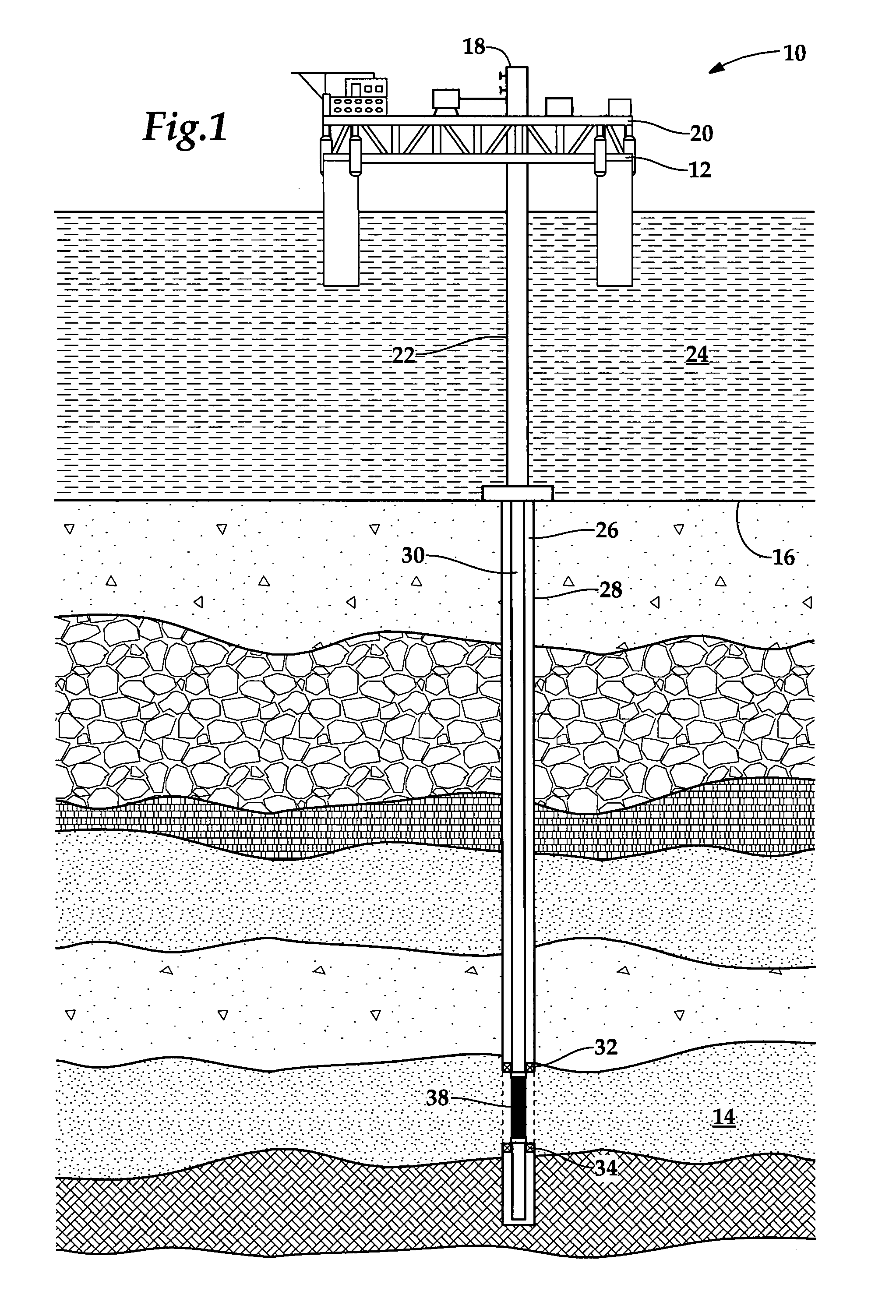
[0033]Referring now to FIG. 1, a sand control screen having a micro-perforated filtration layer in use with an offshore oil and gas production platform is schematically illustrated and generally designated 10. A semi-submersible platform 12 is centered over a submerged oil and gas formation 14 located below sea floor 16. Wellhead 18 is located on deck 20 of platform 12. Well 22 extends through the sea 24 and penetrates the various earth strata including formation 14 to form wellbore 26. Disposed within wellbore 26 is casing 28. Disposed within casing 28 and ext...


PUM


Abstract

A sand control screen (40) includes a perforated base pipe (42) and a filter layer (50) that has micro-perforations (52) therein. The filter layer (50) is attached to the base pipe (42) along the entire length of the filter layer (50). Channels (46) are formed between the base pipe (42) and the filter layer (50) to allow fluid to flow therebetween. The sand control screen (40) is formed by micro-perforating a length of material, such as sheet metal, to form the filter layer (50), creating channels (46) that will allow fluids to flow between the base pipe (42) and filter layer (50), wrapping the filter layer (50) around the base pipe (42), attaching the filter layer (50) to the base pipe (42) along the length of the filter layer (50) and creating a seam between the two edges of the filter layer (50).

Description

TECHNICAL FIELD OF THE INVENTION[0001]This invention relates, in general, to a sand control device used during the production of oil, gas or water and a manufacturing process related to the same and, in particular, to a sand control screen having a micro-perforated filtration layer.BACKGROUND OF THE INVENTION[0002]Without limiting the scope of the present invention, its background will be described with reference to producing fluid from a subterranean formation, as an example.[0003]After drilling each of the sections of a subterranean wellbore, individual lengths of relatively large diameter metal tubulars are typically secured together to form a casing string that is positioned within each section of the wellbore and cemented in place. This casing string is used to increase the integrity of the wellbore by preventing the wall of the hole from collapsing and to prevent movement of fluids from one formation to another formation.[0004]Once the process of drilling and installing casing...

Claims


Application Information

Patent Timeline
Patent Type & Authority Applications(United States)
IPC IPC(8): E21B43/08
CPCE21B43/084
Inventor SIMONDS, FLOYD RANDOLPHDUSTERHOFT, RONALD GLENGARDINER, NICHOLAS HUBERTFERGUSON, CARL BISMARCKGRIGSBY, TOMMY FRANKBOUDREAUX, ERIC PAUL
Owner HALLIBURTON ENERGY SERVICES INC
Why Eureka
Try Eureka