Suction plate and cradle for an automobile having the same

a technology of suction plate and cradle, which is applied in the direction of vehicle components, fastening means, stands/trestles, etc., can solve the problems of difficult to move a cradle, cradle cannot be securely fastened in the second or later position, and prior art as described above, and achieves the effect of convenient mounting and dismounting

Inactive Publication Date: 2008-09-11
LG ELECTRONICS INC
View PDF9 Cites 23 Cited by
  • Summary
  • Abstract
  • Description
  • Claims
  • Application Information

AI Technical Summary

Benefits of technology

[0011]The present invention is conceived to solve the aforementioned problems in the prior art. An object of the present invention is to provi...

Problems solved by technology

However, the prior art as described above has disadvantages as follows.
First, with an adhesion type mount, it is difficult to move a cradle that has been initially mounted to an interior of an automobile to another place in order to remount the cradle.
In addition, in a case where the cradle is remount...

Method used


Image

  • Suction plate and cradle for an automobile having the same
  • Suction plate and cradle for an automobile having the same
  • Suction plate and cradle for an automobile having the same

Examples


first embodiment

[0048]a cradle for an automobile according to the present invention will be described in detail with reference to the accompanying drawings.

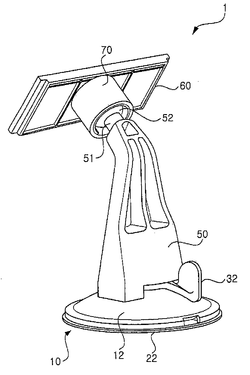
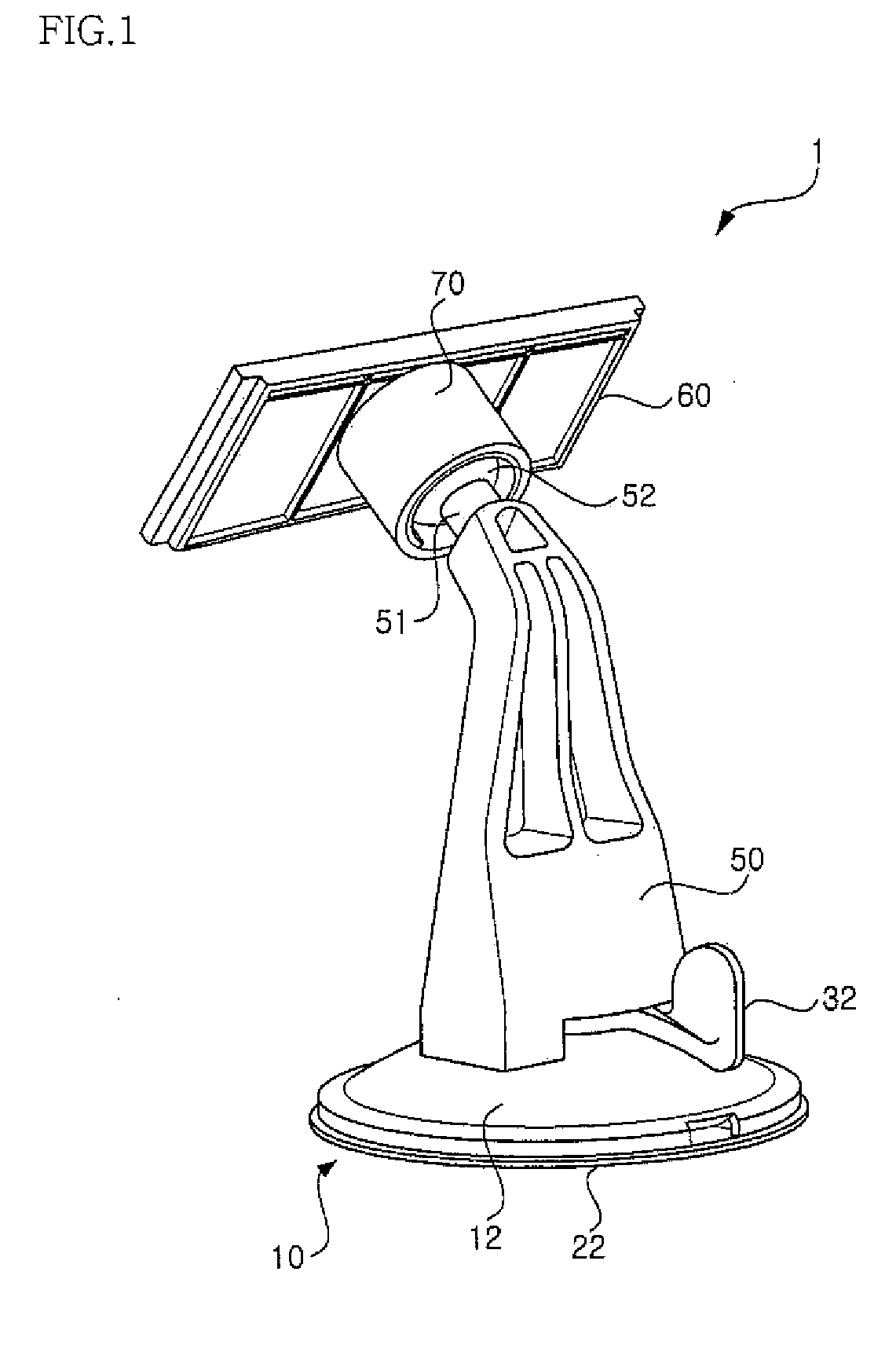
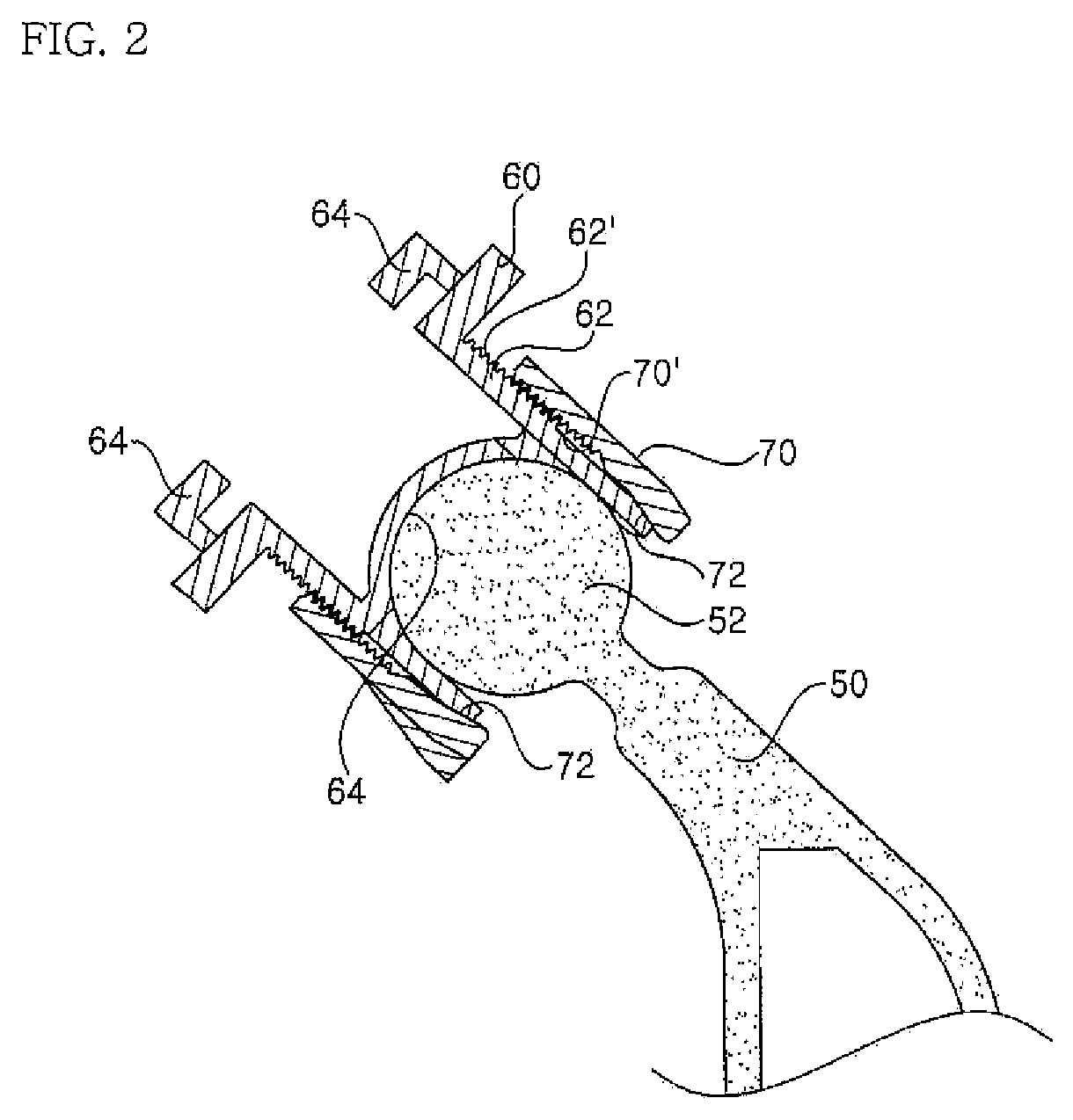
[0049]FIG. 1 is a perspective view of the first embodiment of a cradle for an automobile according to the present invention, FIG. 2 is a partial sectional view showing a state where the first embodiment of the cradle for an automobile according to the present invention is assembled, and FIG. 3 is an exploded perspective view of a first embodiment of a suction plate according to the present invention;

[0050]As shown the figures, a cradle 1 for an automobile comprises a suction plate 10 for fastening and supporting the cradle 1 to a surface on which the cradle is to be mounted; a support body 50 connected to an upper portion of the suction plate 10 to form an entire framework of the cradle; a mounting plate 60 connected to an upper end of the support body 50 for supporting various devices for an automobile thereon; and a holder 70 coupled to the mo...

second embodiment

[0064]In the meantime, the structure of the suction plate will be described below with reference to FIGS. 5a and 5b.

[0065]A suction plate 110 is provided with a housing 112 defining an entire external appearance of the suction plate 110. The housing 112 has a dish-shape formed by depressing a general circular plate member to be concave. A suction member 122, which will be described later, is vertically moved relative to the housing 112 in the concave portion thereof.

[0066]A through hole 114 is formed in a central portion of the housing 112 so that an elevating shaft 126 to be described later passes through the through hole. In addition, a stopper 116 is formed around the through hole 114. The stopper 116 restricts a rotational range of an operating lever 132, which will be described later. In addition, the stopper 116 enables the operating lever 132 to maintain a suction state or a suction release state of the suction member 122 to be described later.

[0067]A coupling surface 119 on...


PUM


Abstract

A suction plate and a cradle for an automobile having the same, the suction plate including a housing provided with a boss protruding in one direction, the boss having a through hole formed to pass through a side thereof; a suction member installed at a lower portion of the housing to be moved relative to the housing, the suction member having a central shaft inserted in the boss, the central shaft having a central hole formed thereon to pass through a side thereof; an elastic member provided in an upper portion of the central shaft to provide elastic force in a direction in which the suction member and the housing go away from each other; and an operating lever provided in the housing rotatably within a certain angular range to adjust relative movement of the housing and the suction member.

Description

CROSS REFERENCE TO RELATED APPLICATIONS[0001]The present application claims priority to Korean patent application KR 2007-0020426, filed on Feb. 28, 2007 and KR 2007-0042790, filed on May 2, 2007, the entire contents of which is hereby incorporated by reference.BACKGROUND OF THE INVENTION[0002]1. Field of Invention[0003]The present invention relates to a cradle, and more particularly, to a suction plate for mounting various kinds of devices operated by a driver and used in an interior of an automobile and, a cradle for an automobile having the suction plate.[0004]2. Description of the Prior Art[0005]In recent times, a navigation systems providing a driver with overall information regarding traffic conditions through global positioning system satellites, or a terrestrial digital multimedia broadcasting terminal, a satellite digital multimedia broadcasting terminal or the like through which users can watch a broadcasting program in driving, have come into wide use.[0006]As the aforeme...

Claims


Application Information

Patent Timeline
IPC IPC(8): B25B11/00
CPCF16B47/006F16M11/041F16M11/14F16M13/022B60R2011/0089B60R2011/0056B60R2011/0073B60R2011/0085B60R11/0258
Inventor KIM, JUNG-SIK
Owner LG ELECTRONICS INC
Why Eureka
Try Eureka