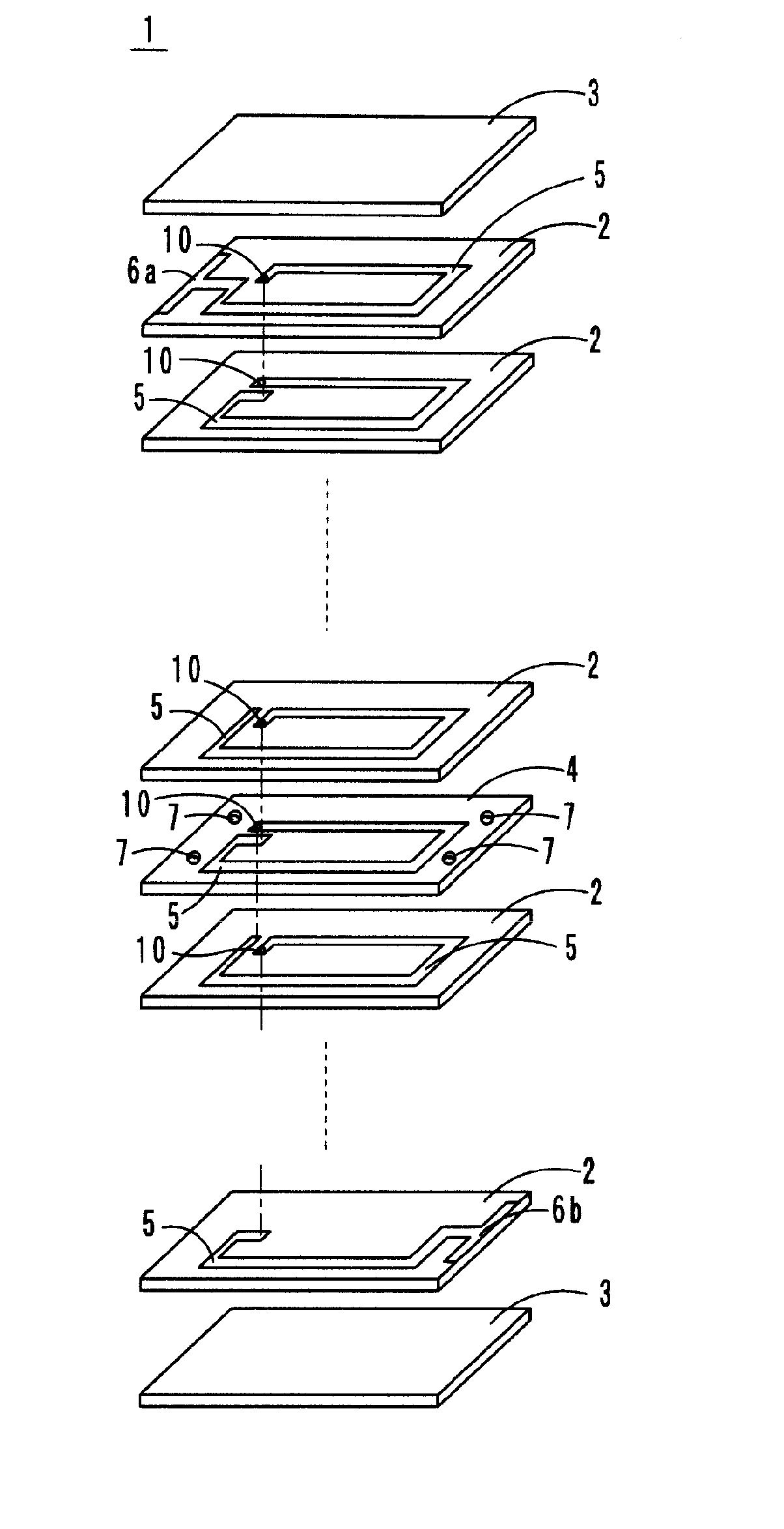
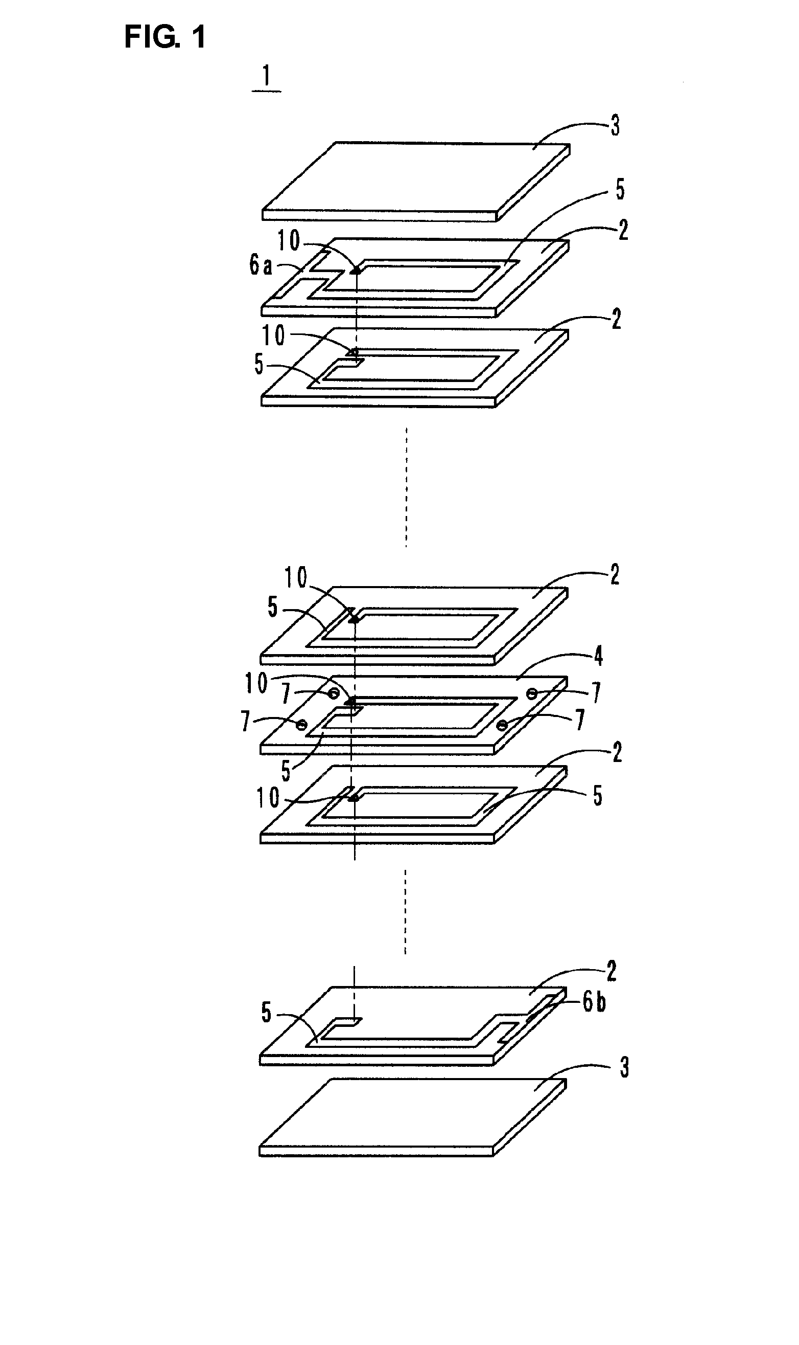
[0008]According to a preferred embodiment of the present invention, a multilayer coil component includes a coil formed by stacking magnetic layers and a low-magnetic-permeability layer, the magnetic layers having coil conductors provided therein, the low-magnetic-permeability layer having a lower magnetic permeability than the magnetic layers, and the coil conductors being electrically connected to each other, the low-magnetic-permeability layer is disposed between the magnetic layers, holes or recesses are provided in a main surface of the low-magnetic-permeability layer, and the magnetic layers adjacent to the low-magnetic-permeability layer are in contact with inner
peripheral surfaces of the holes or the recesses. Since the magnetic layers adjacent to the low-magnetic-permeability layer are in contact with the inner
peripheral surfaces of the holes or the recesses, an anchoring effect is provided between the magnetic layers and the low-magnetic-permeability layer. As a result, the occurrence of cracks or
delamination between the magnetic layers and the low-magnetic-permeability layer is suppressed.
[0010]Preferably, side surfaces that define the inner peripheral surfaces of the holes or the recesses are continuously connected to each other. If the side surfaces that define the recesses or the holes are disconnected from each other, the magnetic layers and the low-magnetic-permeability layer do not contact each other at the disconnected portions. As a result, the anchoring effect provided between the magnetic layers and the low-magnetic-permeability layer is reduced. Therefore, in order to achieve an increased anchoring effect, preferably, the side surfaces that define the inner peripheral surfaces of the holes or the recesses are continuously connected to each other.
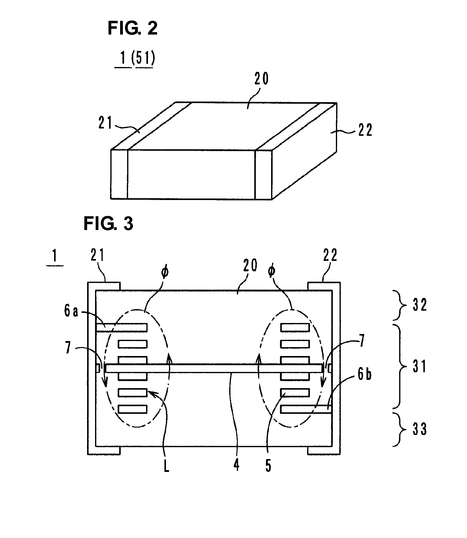
[0011]Preferably, the holes or the recesses are provided in regions outside the coil when viewed in a stacking direction. Furthermore, preferably, the holes or the recesses are provided in the proximity of a periphery of the low-magnetic-permeability layer. At the holes or the recesses, magnetic resistance is less than in the low-magnetic-permeability layer around the holes or the recesses. By providing such regions of low magnetic resistance outside the coil or in the proximity of the periphery of the low-magnetic-permeability layer, as compared to when such regions are provided inside the coil, leakage of
magnetic flux to the outside of the multilayer coil component is reduced. As a result, a high
inductance can be achieved in the multilayer coil component.
[0012]Preferably, the low-magnetic-permeability layer has a rectangular or substantially rectangular shape, and the holes or the recesses are provided in the proximity of longer sides of the low-magnetic-permeability layer. The distance from the center of the coil to the longer sides of the low-magnetic-permeability layer is less than the distance from the center of the coil to the shorter sides of the low-magnetic-permeability layer. Therefore, a
magnetic flux generated by the coil tends to leak more from the longer sides than from the shorter sides. Thus, the holes or the recesses are provided in the proximity of the low-magnetic-permeability layer so that magnetic resistance in the proximity of the longer sides is reduced. Accordingly, leakage of
magnetic flux is effectively reduced, so that the
inductance of the multilayer coil component can be increased.
[0013]Preferably, the low-magnetic-permeability layer has a rectangular or substantially rectangular shape, external electrodes are provided, the external electrodes being provided on surfaces of a multilayer block formed by stacking the magnetic layers and the low-magnetic-permeability layer, and the external electrodes being electrically connected to the coil, the holes or the recesses are provided in the proximity of either longer sides or shorter sides of the low-magnetic-permeability layer, and the external electrodes are provided on side surfaces of the multilayer block, the side surfaces including sides of the low-magnetic-permeability layer that are different from the sides of the low-magnetic-permeability layer along which the holes or the recesses are provided. Furthermore, preferably, the holes or the recesses are provided in the proximity of the longer sides of the low-magnetic-permeability layer, and the external electrodes are provided on side surfaces of the multilayer block including the shorter sides of the low-magnetic-permeability layer. By providing the holes or recesses or the external electrodes in the proximity of the individual sides as described above, leakage of magnetic flux from the side surfaces of the multilayer block is effectively suppressed. As a result, the inductance of the multilayer coil component can be increased.
[0015]The multilayer coil component according to preferred embodiments of the present invention can be manufactured by the following manufacturing method. Specifically, a method of manufacturing a multilayer coil component including a multilayer block having a coil therein includes a step of forming magnetic layers and a low-magnetic-permeability layer having a lower magnetic permeability than the magnetic layers, a step of forming coil conductors in main surfaces of the magnetic layers, a step of forming holes or recesses in a main surface of the low-magnetic-permeability layer, and a step of forming a multilayer block in which the magnetic layers are in contact with inner peripheral surfaces of the holes or the recesses by stacking the magnetic layers and the low-magnetic-permeability layer so that the low-magnetic-permeability layer is disposed between the magnetic layers. According to the manufacturing method, the multilayer coil component can be effectively manufactured.


