
System and method for parking infraction detection

a technology for parking infractions and automatic detection, applied in the field of parking enforcement, can solve the problems of enforcement officers' efforts, difficult upkeep of parking meters, and high installation costs, and achieve the effect of reducing the number of infractions

Inactive Publication Date: 2008-09-11
FRANKLIN WILLIAM +5
View PDF42 Cites 55 Cited by
  • Summary
  • Abstract
  • Description
  • Claims
  • Application Information

AI Technical Summary

Problems solved by technology

While many people have grown accustomed to the use of parking meters, parking meters are difficult to upkeep and expensive to install, as each parking space requires a parking meter.
This requires a great deal of manual effort, and the parking enforcement officer's efforts are often hampered by weather conditions, leaving the enforcement officer prone to injury as they are continuously walking between vehicles.
The use of parking enforcement officers is also inefficient, as a parking enforcement officer is only able to cover a limited number of cars in a given shift.
The process by which an officer determines whether a vehicle has moved is very labour intensive and inefficient, and only a few cars may be monitored regularly.
License plate recognition is prone to be inefficient for many reasons.
License plate recognition involves taking images of the license plate and is subject to poor image resolution as the license plate may be too far away or at too acute of an angle from the camera taking the picture.
Poor lighting conditions and reflections are two other reasons why license plate recognition proves to be an inefficient method to rely on when attempting to uniquely identify vehicles.
These difficulties when combined with the natural dirt, sleet or snow that may cover the license plate, make the unique identification of vehicles that much more difficult.

Method used


Image

  • System and method for parking infraction detection
  • System and method for parking infraction detection
  • System and method for parking infraction detection

Examples


Embodiment Construction

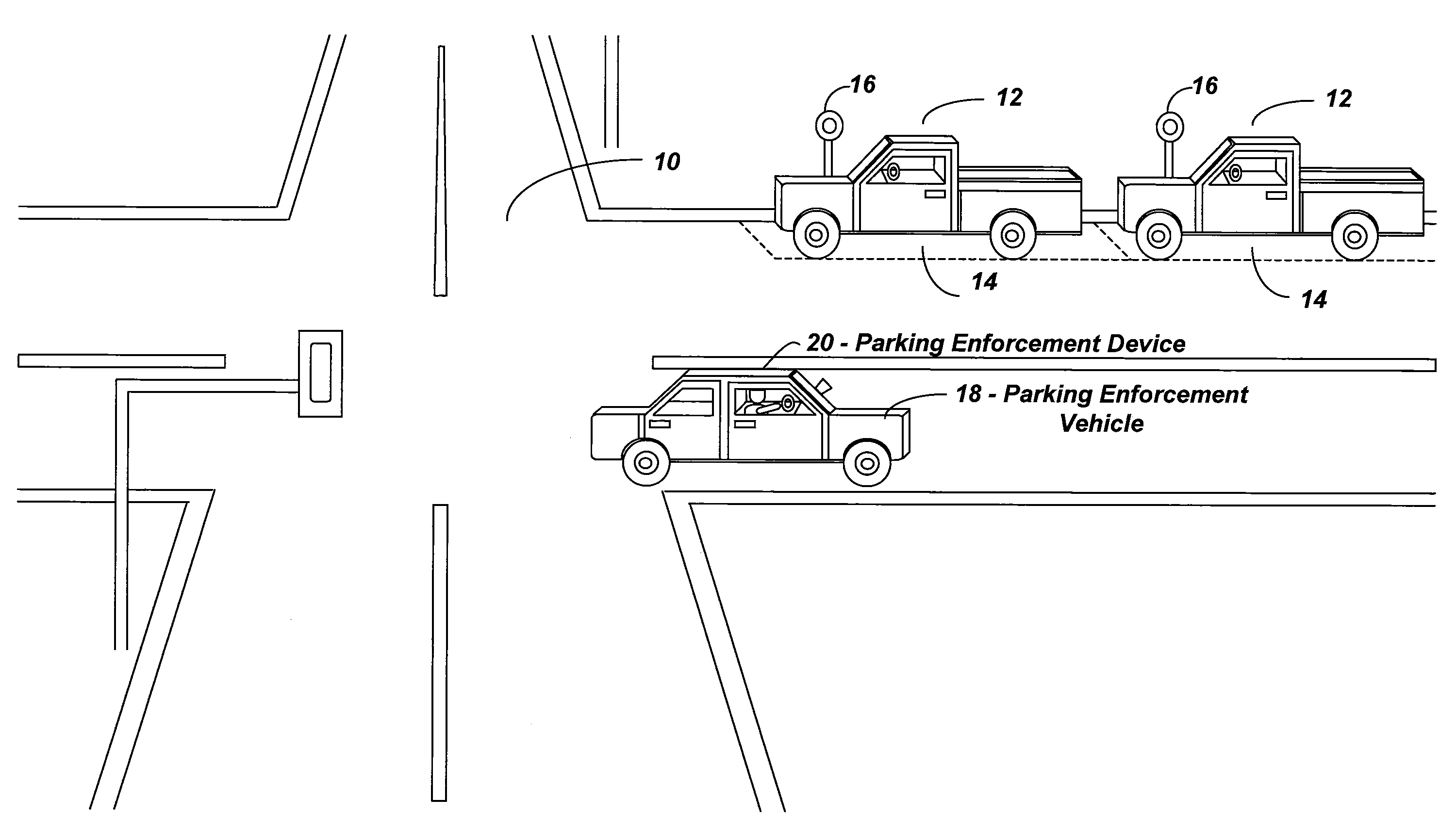
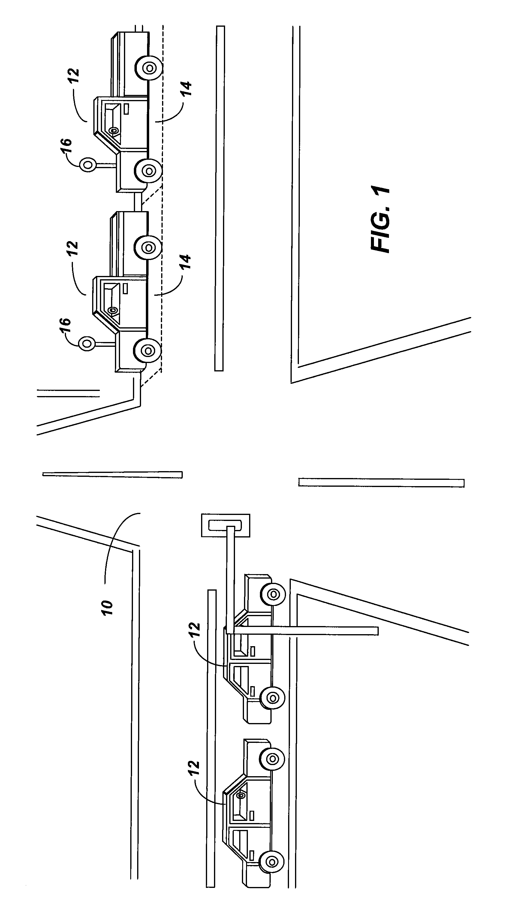
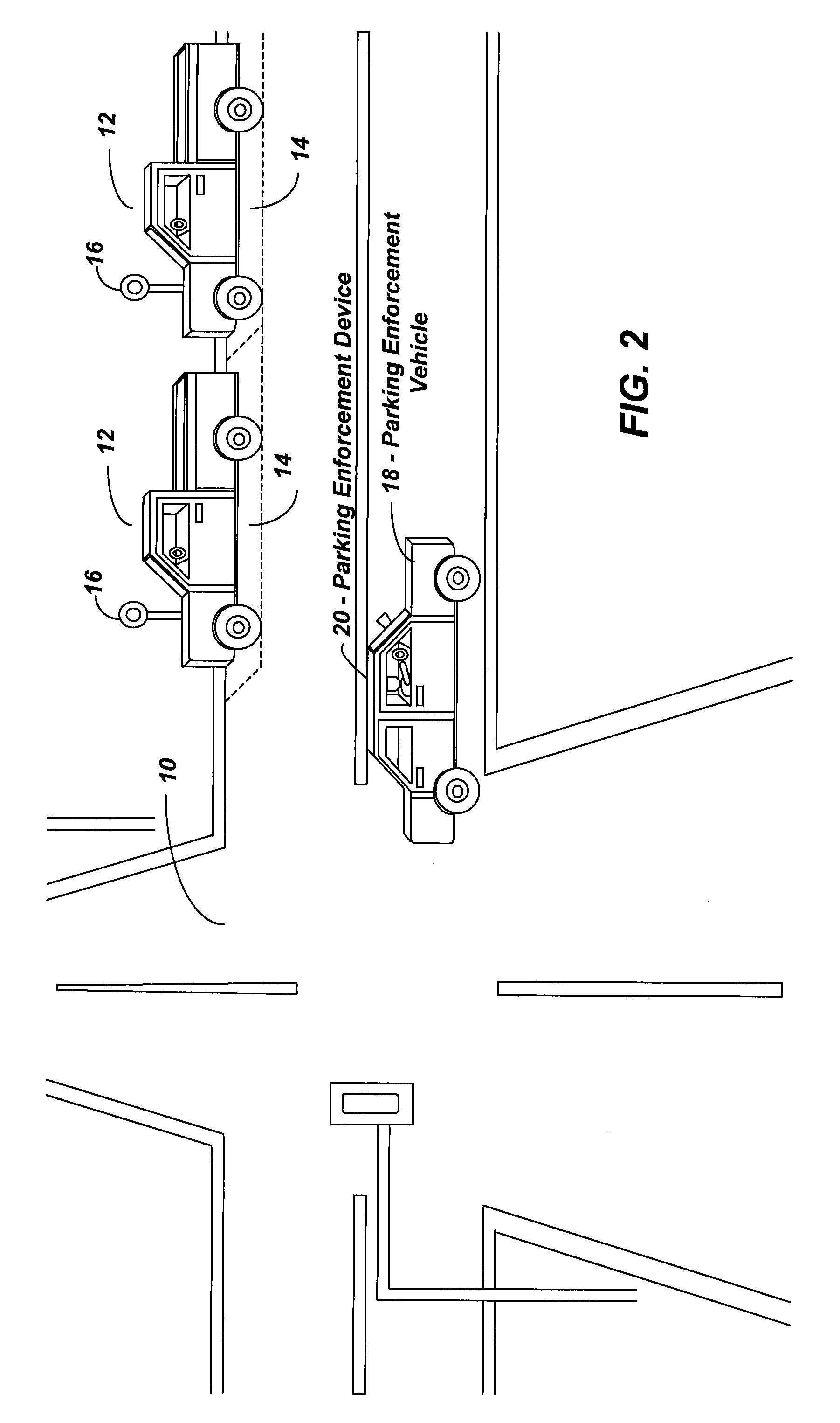
[0035]Reference is now made to FIG. 1, where a diagram illustrating vehicles parked on a street is shown. FIG. 1 illustrates a roadway 10, upon which vehicles 12 are driven, and parked in parking spaces 14. The term roadway 10 is used to refer to any transportation route upon which a vehicle 12 may be driven and parked. Parking spaces 14 as shown in FIG. 1 are used to refer to the designated areas upon a roadway where parking is allowed. The parking space 14 may be used based on the respective rules that govern the parking of vehicles 12. The parking regulations may specify that the parking spaces may be occupied only at certain times of the day, or occupied at certain times of the day based on a fee for use system. Also, shown in FIG. 1, is a parking meter 16. The parking meter 16 provides a mechanism by which parking enforcement authorities may administer parking regulations. The parking meter 16 allows motorists to purchase an amount of time by entering money into the meter, whic...


PUM


Abstract

The invention relates to a system and method for detecting parking infractions. It comprises computing one or more measurements associated with a stationary object found at a first location; classifying the stationary object as being representative of a vehicle parked at the first location based on the one or more measurements associated with the stationary object; capturing one or more images of the vehicle parked at the first location; processing the one or more images of the vehicle to extract one or more present vehicle identifiers associated with the vehicle, and recording a time the one or more images were taken, a co-ordinate set associated with the first location and the one or more identifiers associated with the vehicle; determining a time duration for which parking is allowed at the first location; and comparing the present vehicle identifiers with previously recorded vehicle identifiers associated with the first location to determine if the vehicle has been parked at the first location for a period exceeding the time duration.

Description

[0001]This application is a Continuation Application of U.S. application Ser. No. 11 / 328,113 filed Jan. 10, 2006, which claims priority from U.S. Provisional Application Ser. No. 60 / 642,102 filed Jan. 10, 2005, and U.S. Provisional Application Ser. No. 60 / 679,228 filed May 10, 2005, all of which are herein incorporated by reference.FIELD OF THE INVENTION [0002]The invention relates generally to the field of parking enforcement, and more specifically to systems and methods for the automatic detection of parking infractions.BACKGROUND OF THE INVENTION [0003]Parking regulations are enacted for multiple purposes. Purposes for which parking regulations are enacted and enforced include, generating revenue for the appropriate authorities, easing congestion on roadways, facilitating vehicle turnover and hence improving foot traffic for business owners, and for controlling parking on residential streets.[0004]By regulating the parking of vehicles on roadways, the appropriate governing author...

Claims


Application Information

Patent Timeline
Patent Type & Authority Applications(United States)
IPC IPC(8): G08G1/017
CPCB60R9/10G08G1/127G08G1/0175G06Q30/0284
Inventor FRANKLIN, WILLIAMBETHUNE, JEFFLEUNG, RAPHAELNUCARO, ANTONIOFRANKLIN, LYLEBOSANAC, ALEX
Owner FRANKLIN WILLIAM
Learn More