Liquid ejection apparatus and liquid ejection surface maintenance method

Inactive Publication Date: 2008-09-11
FUJIFILM CORP
View PDF8 Cites 60 Cited by
  • Summary
  • Abstract
  • Description
  • Claims
  • Application Information

AI Technical Summary

Benefits of technology

[0009]The present invention has been contrived in view of these circumstances, an object thereof being to provide a liquid ejection apparatus and a liquid ejection surface maintenance method, whereby ink which has been flowed out from nozzles onto the liquid ejection surface can be caused to spread uniform

Problems solved by technology

In an inkjet recording apparatus, ink is liable to adhere to the ink ejection surface of the inkjet head, and if residual ink of this kind solidifies, then it can cause ejection abnormalities, such as abnormalities in the ink ejection volume or abnormalities in the ejection direction.
In performing wiping operation by means of a blade, it is possible readily to remove ink in liquid state which has adhered to the ink ejection surface, but it is difficult to remove ink which has cured to a certain extent, and it is not possible to obtain a satisfactory cleaning effect.
Supposing that wiping is carried out by increasing the force with which the blade is pressed against the ink ejection surface, then although it is possible to remove the cured ink adhering to the ink ejection surface to a certain extent, there is a possibility that the liquid-phobic film formed on the ink ejection surface will be damaged and that ejection abnormalities will be caused by the resulting defects in the liquid-phobic film.
However, in the invention described in Japanese Patent Application Publication No. 7-096604, although it is possible to flow out the ink from the selected nozzles onto a very small region (regions in the vicinity of the selected nozzles) of the ink ejection surface, it is difficult to spread the ink to regions relatively distant from the selected nozzles, and it is not possible completely to remove adhering material, such as cured ink, which is attached to a portion that is relatively distant from the selected nozzles, due to the creation of mist, or the like.
Moreover, in the case of an inkjet head

Method used


Image

  • Liquid ejection apparatus and liquid ejection surface maintenance method
  • Liquid ejection apparatus and liquid ejection surface maintenance method
  • Liquid ejection apparatus and liquid ejection surface maintenance method

Examples


Example

Second Embodiment

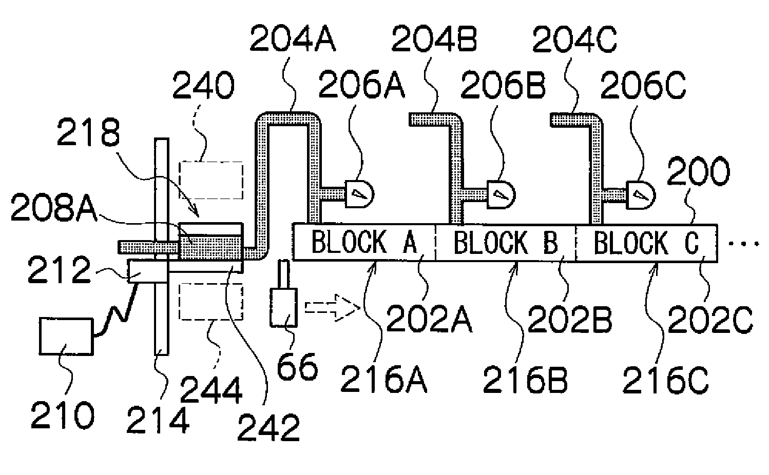
[0211]Next, a second embodiment of the present invention will be described. FIG. 12 is a structural diagram showing the approximate composition of a portion of a head 200 and an ink supply system according to a second embodiment of the present invention. In this second embodiment, parts which are the same as or similar to the first embodiment described above are labeled with the same reference numerals and further explanation thereof is omitted here.

[0212]The head 200 shown in FIG. 12 is constituted of a plurality of head blocks (corresponding to “nozzle block) 202 (202A, 202B, 202C, . . . ) and the respective head blocks 202 are arranged in one row in the breadthways direction of the recording paper 16. FIG. 12 depicts three head blocks, but it is possible to provide a greater number of head blocks, and it is also possible to provide two head blocks.

[0213]Ink supply channels 204 (204A, 204B, 204C, . . . ) are connected respectively to the head blocks 202, and press...

Example

Third Embodiment

[0248]Next, a third embodiment of the present invention will be described. In the third embodiment, the same composition of the inkjet recording apparatus, head structure, composition of the ink supply system and overall system composition can be adopted as in the first embodiment, and therefore further explanation thereof is omitted here. For the control of the change of the internal pressure of the head (the composition of the head internal pressure control), it is possible to adopt either the mode described in the first embodiment or the mode described in the second embodiment.

[0249]In the third embodiment of the present invention, a composition is adopted in which the adhering material that is attached to the ink ejection surface is removed by a method other than wiping by the blade 66.

[0250]Problems regarding the deflection of the flight direction of the ink droplets ejected from the nozzles or the like may arise due to adherence of ink mist to the end faces of ...


PUM


Abstract

A liquid ejection apparatus includes: a liquid ejection head which includes a nozzle ejecting liquid, a pressure chamber connected to the nozzle and arranged in a liquid ejection surface of the liquid ejection head, and a pressure application device applying pressure to the liquid inside the pressure chamber; an internal pressure adjustment device which adjusts an internal pressure of the liquid ejection head; and a pressure control device which controls the internal pressure adjustment device and the pressure application device so as to spread the liquid over the liquid ejection surface of the liquid ejection head. The internal pressure adjustment device adjusts the internal pressure of the liquid ejection head to a positive pressure so as to still hold the liquid on the nozzle while protruding the liquid from the liquid ejection surface. The pressure application device then applies the pressure to the liquid inside the pressure chamber for a pressure application duration so as not to cause the liquid to be ejected from the nozzle but to flow out the liquid from the nozzle onto the liquid ejection surface, while the internal pressure adjustment device is adjusting the internal pressure to the positive pressure. The pressure application device then stops applying the pressure to the liquid inside the pressure chamber after the pressure application duration, while the internal pressure adjustment device is adjusting the internal pressure to the positive pressure.

Description

BACKGROUND OF THE INVENTION[0001]1. Field of the Invention[0002]The present invention relates to a liquid ejection apparatus and a liquid ejection surface maintenance method, and more particularly, to technology for cleaning the liquid ejection surface of a liquid ejection head which ejects liquid droplets from nozzles.[0003]2. Description of the Related Art[0004]In general, an inkjet recording apparatus which forms a desired image by ejecting ink droplets from an inkjet head onto a recording medium has been known as a generic image forming apparatus. In an inkjet recording apparatus, ink is liable to adhere to the ink ejection surface of the inkjet head, and if residual ink of this kind solidifies, then it can cause ejection abnormalities, such as abnormalities in the ink ejection volume or abnormalities in the ejection direction. Hence, it is necessary to carry out periodic maintenance (cleaning) of the ink ejection surface of the inkjet head. One method of cleaning the ink ejecti...

Claims


Application Information

Patent Timeline
IPC IPC(8): B41J2/165B41J29/38
CPCB41J2/16526B41J2/16535B41J2/16585B41J29/393B41J2/17596B41J29/38B41J2/175B41J2/2114
Inventor INOUE, HIROSHI
Owner FUJIFILM CORP
Why Eureka
Try Eureka