Resin wound component

Inactive Publication Date: 2008-09-11
JTEKT CORP
View PDF48 Cites 13 Cited by
  • Summary
  • Abstract
  • Description
  • Claims
  • Application Information

AI Technical Summary

Benefits of technology

[0009]An object of the invention is to provide a resin wound component that is designed to prevent strength decrease of the ring-shaped surrounding portion for surrounding axial end surfaces of outer circumferential e

Problems solved by technology

However, internal stress (internal stress caused by a thermal expansion difference between the resin portion and the metal member) is concentrated in a gate mark portion of the resin portion in both types, and thus a problem arises in that a crack may easily occur in the gate mark port

Method used


Image

  • Resin wound component
  • Resin wound component
  • Resin wound component

Examples


Example

[0036]Hereinafter, a resin wound component according to an exemplary embodiment of the invention will be described in detail with reference to the accompanying drawings.

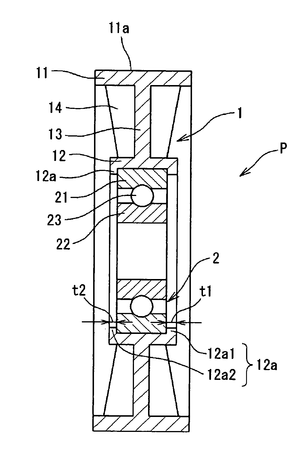
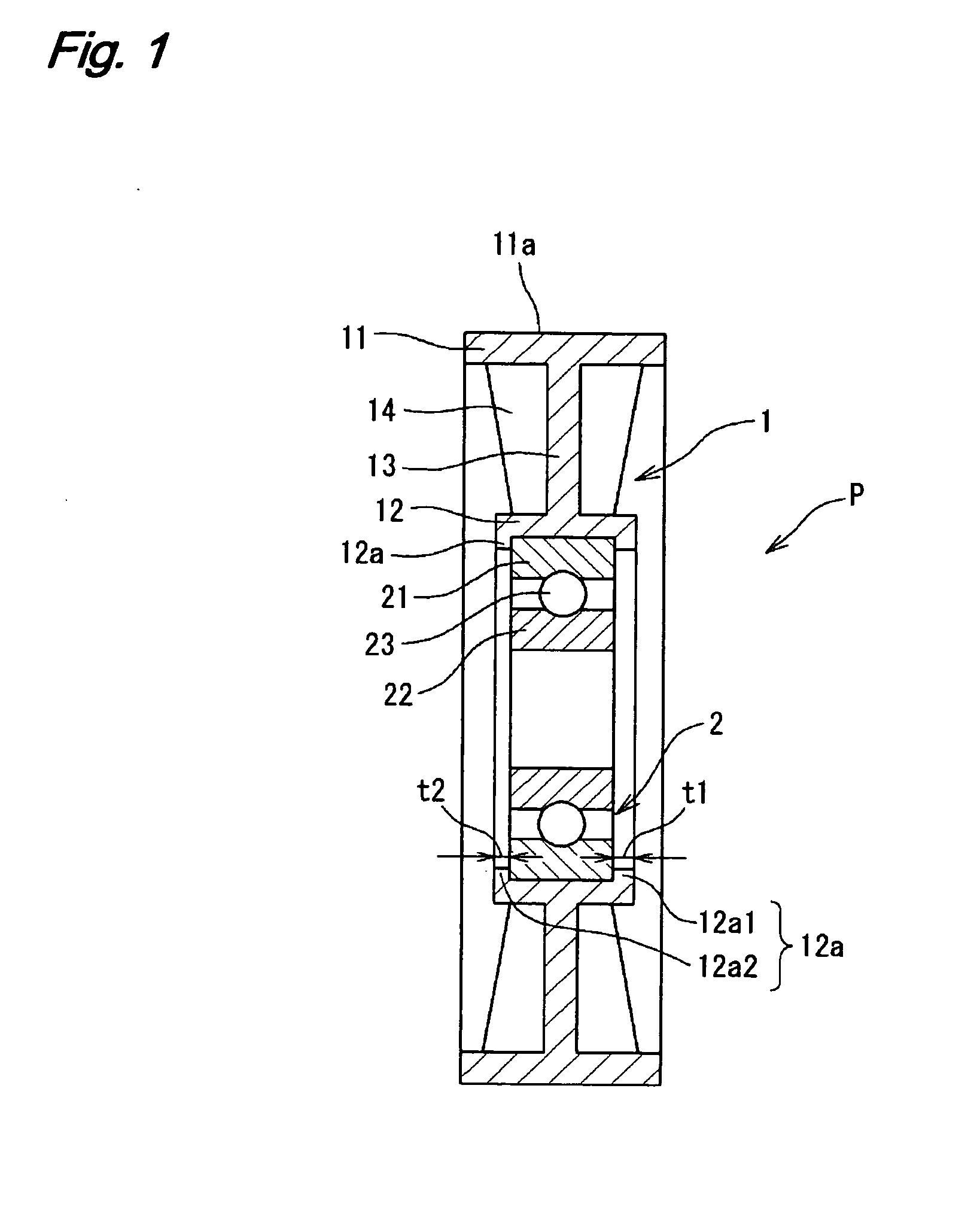
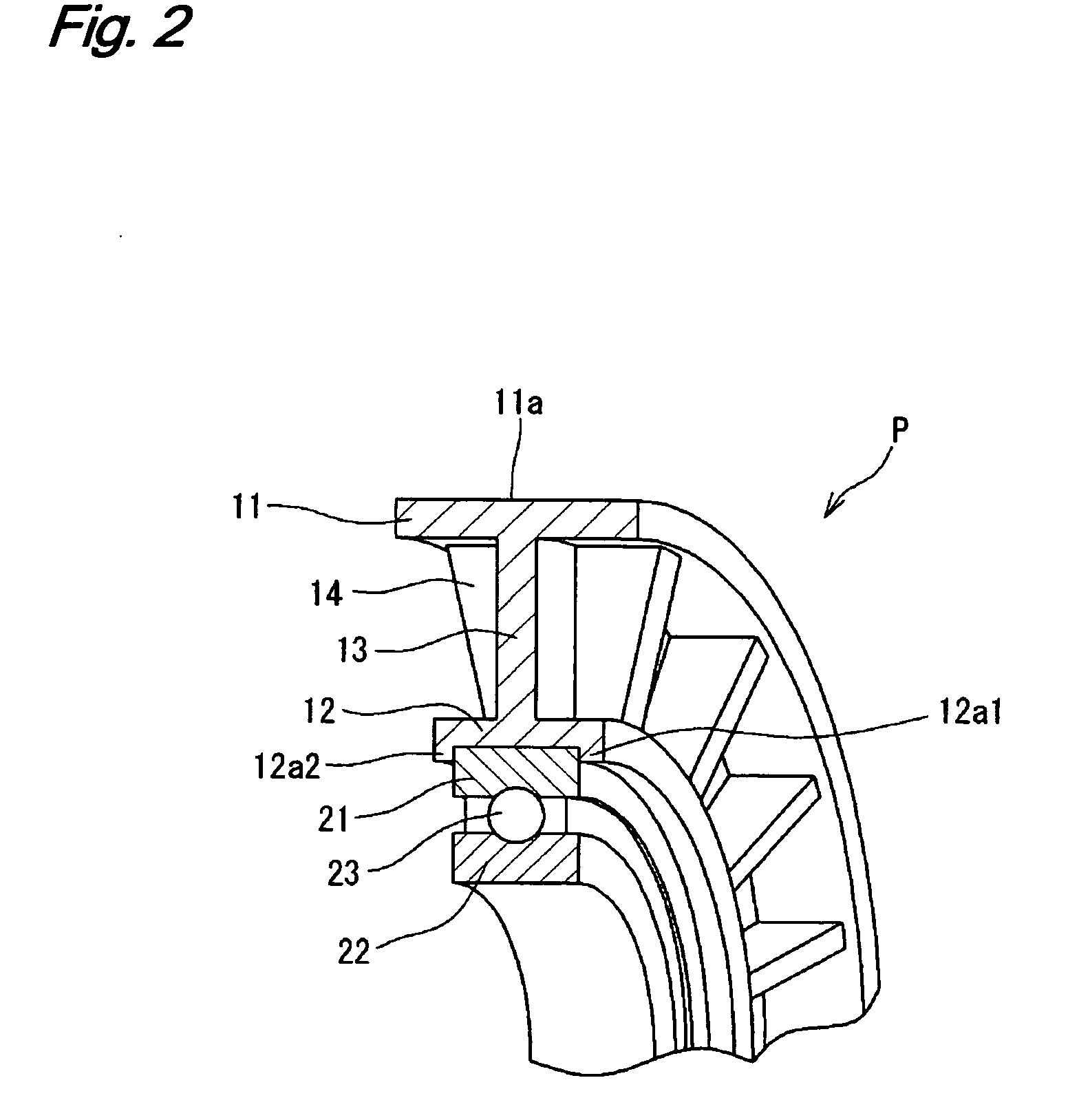
[0037]FIG. 1 is a sectional view illustrating a resin pulley P according to an embodiment of the invention. FIG. 2 is a partially perspective view illustrating the same. The resin pulley P is used for example as a pulley of an ancillary drive belt of an automobile engine. The resin pulley P is configured such that a rolling bearing 2 as a metal member is inserted into an inner circumference of a ring-shaped resin portion 1. An outer circumferential cylindrical portion 11 having a belt guide surface 11a formed in an outer circumference thereof is formed in an outer circumferential side of the resin portion 1. An inner circumferential cylindrical portion 12 for fixing an outer circumference of an outer ring 21 of the rolling bearing 2 is formed in an inner circumference thereof. The inner circumferential cylindrical po...


PUM

PropertyMeasurementUnit
Thicknessaaaaaaaaaa
Circumferenceaaaaaaaaaa

Abstract

A resin wound component is configured such that a ring-shaped resin portion is integrally formed with an outer circumference of a ring-shaped metal member by a film gate. The resin portion includes a ring-shaped surrounding portion for surrounding axial end surfaces of outer circumferential edges of the ring-shaped metal member. At this time, the thickness of a ring-shaped surrounding portion on the gate side is configured to be larger than that of a ring-shaped surrounding portion on an opposite side to the gate.

Description

BACKGROUND OF THE INVENTION[0001]1. Field of the Invention[0002]The present invention relates to a resin wound component, and more particularly, to a resin wound component in which a ring-shaped resin portion is integrally formed with an outer circumference of a ring-shaped metal member by (through) a film gate.[0003]2. Related Art[0004]Conventionally, for example, as a pulley of an ancillary drive belt of an automobile engine, a resin wound component has been used in which a metal member such as a rolling bearing or a metal hub is integrally formed with an inner circumference of a ring-shaped resin portion (pulley) having a belt guide surface formed in an outer circumference thereof.[0005]Such a resin wound component is manufactured by an insert molding for simultaneously integrating the metal member with the resin portion formed by an injection molding. As a gate type, a pin point type or a side gate type has been used. However, internal stress (internal stress caused by a thermal...

Claims


Application Information

Patent Timeline
IPC IPC(8): F16H55/00F16H55/36B29C65/70
CPCB29C45/0046B29C45/1459B29C45/2708F16H55/48B29K2105/06F16C13/006B29C2045/2714F16C19/06F16C35/067F16C2361/63
Inventor MURAO, SATORU
Owner JTEKT CORP
Why Eureka
Try Eureka