
Retort cup

Inactive Publication Date: 2012-05-24
TOPPAN PRINTING CO LTD
View PDF6 Cites 39 Cited by
  • Summary
  • Abstract
  • Description
  • Claims
  • Application Information

AI Technical Summary

Benefits of technology

[0051]According to the retort cup related to the aspect of the above invention, exposed portions of the end edges of the barrel portion forming blank on the side of the bottom portion are sealed to protect the end surfaces.
[0052]Thereby, since the paper end surfaces of the barrel portion forming blank on the side of the bottom portion are covered, the liquid in the retort cup is prevented from permeating from the paper end surfaces and wetting the paper. As a result, the strength of the paper layer does not deteriorate. Additionally, since not only the permeation from the inside of the retort cup but also the permeation from the outside is prevented, it is possible to provide a retort cup having water resistance which withstands boiling, retort sterilization, or soaking and cooling in water.
[0053]Additionally, according to the retort cup related to this aspect, the end edge extending portions provided such that the thermoplastic resin layers laminated on the base sheet extend with a predetermined width along the end edges are provided at both facing end edges of the barrel portion forming blank. Therefore, sealing of the base ends can be performed. Additionally, this sealing can be reliably performed by being brought into close contact with and thermally pressure-bonded to the base of the other end which overlaps in the attached barrel overlap portion. Moreover, peeling-off between the layers and deterioration of appearance, which are caused as the end edge extending portions of the attached barrel overlap portion are isolated from the blank, can be avoided.
[0054]Additionally, according to the retort cup related to this aspect, the inner end edge extending portion in the attached barrel overlap portion of the barrel portion forming blank is folded back to the outside of the retort cup and is pressure-bonded in the state of being located between the inner end edge and the outer end edge, whereby the inner end edge is covered with the end edge extending portion. As a result, penetration of water can be more reliably prevented.
[0055]Moreover, the end of the inner end edge extending portion is sealed between the outer base and the inner base, so that exposure of the end can be prevented. Particularly, for example, when the thermoplastic resin layer on the inner surface of the base has a laminated structure including a gas barrier layer made of metal, an inorganic substance, or the like, with no water resistance or gas resistance, protection of the resin layer can be performed.
[0056]Additionally, according to the retort cup related to this aspect, the outer end edge extending portion in the attached barrel overlap portion of the barrel portion forming blank is folded back to the inside of the retort cup and is pressure-bonded in the state of being located between the inner end edge and outer end edge, whereby the end edge outside the joining surface of the bases of the barrel portion is covered with the end edge extending portion. As a result, penetration of water can be more reliably prevented.

Problems solved by technology

Additionally, in order to trim a skived end surface on a straight line, it is difficult to perform cup forming simultaneously when a cup forming machine performs the skive-hemming process.
As such, the skive-hemming process involves complicated working processes.
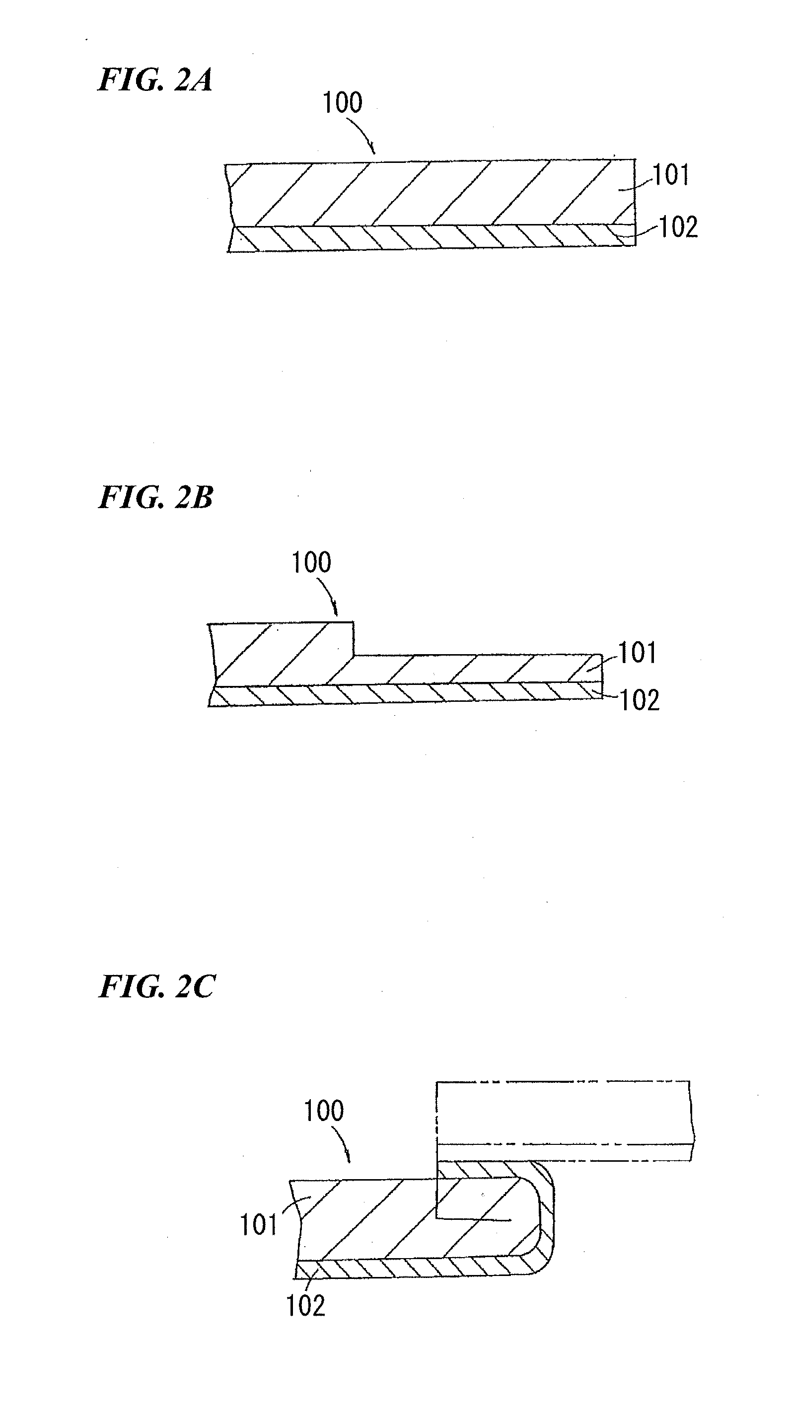
Moreover, complete removal of debris generated by skiving (cutting) the paper base 101 is difficult.
Since management of skive depth is difficult in the skive-hemming process, there is a case where a scrap from the skived portion is generated after the forming.
As a result, there is a problem in that side sealing or the like is not stable.
In addition, in order to use glue for fold-back bonding after skiving in the skive hemming, management of the amount, position, or the like of the glue is difficult.
For this reason, the original purpose of covering the end surfaces of the paper base cannot be sufficiently achieved.
Additionally, since the finish as a cup-like paper container is poor, there is a problem in that a defect is caused in the appearance.
Therefore, when the lid member is overlapped with the top surface of the flange portion, and is heated and sealed, sealing cannot be reliably performed due to the stepped portion.
Additionally, there are problems such as the finish as a cup-like container being poor, and a defect is caused in the appearance.
However, the amount of resin required for bonding the lid member may be insufficient merely by providing the cutout portion in the upper portion of the lateral end edge of the barrel member which does not provide the resin portion.
Moreover, the problem that the sealing using resin of the end surface of the barrel member in the upper flange portion of the attached barrel overlap portion becomes easily imperfect is left unsolved.
For this reason, when the lid member is overlapped with the top surface of the flange portion, and is heated and sealed, sealing cannot be reliably performed due to the stepped portion.
However, a problem that the barrier property of the end surface of the lower end edge of the barrel member in a container bottom surface portion of the cup-like container is insufficient is left unsolved in terms of the protection of the end surface of the paper base.
Therefore, the cup is weak in terms of penetration of water through the paper end surface.

Method used


Image

  • Retort cup
  • Retort cup
  • Retort cup

Examples


first embodiment

(1) First Embodiment

[0145]A retort cup related to a first embodiment of the invention will be described below with reference to the drawings.

[0146]The retort cup related to the present embodiment is made up of a base sheet based on paper which has thermoplastic resin layers provided on the inner and outer surfaces thereof.

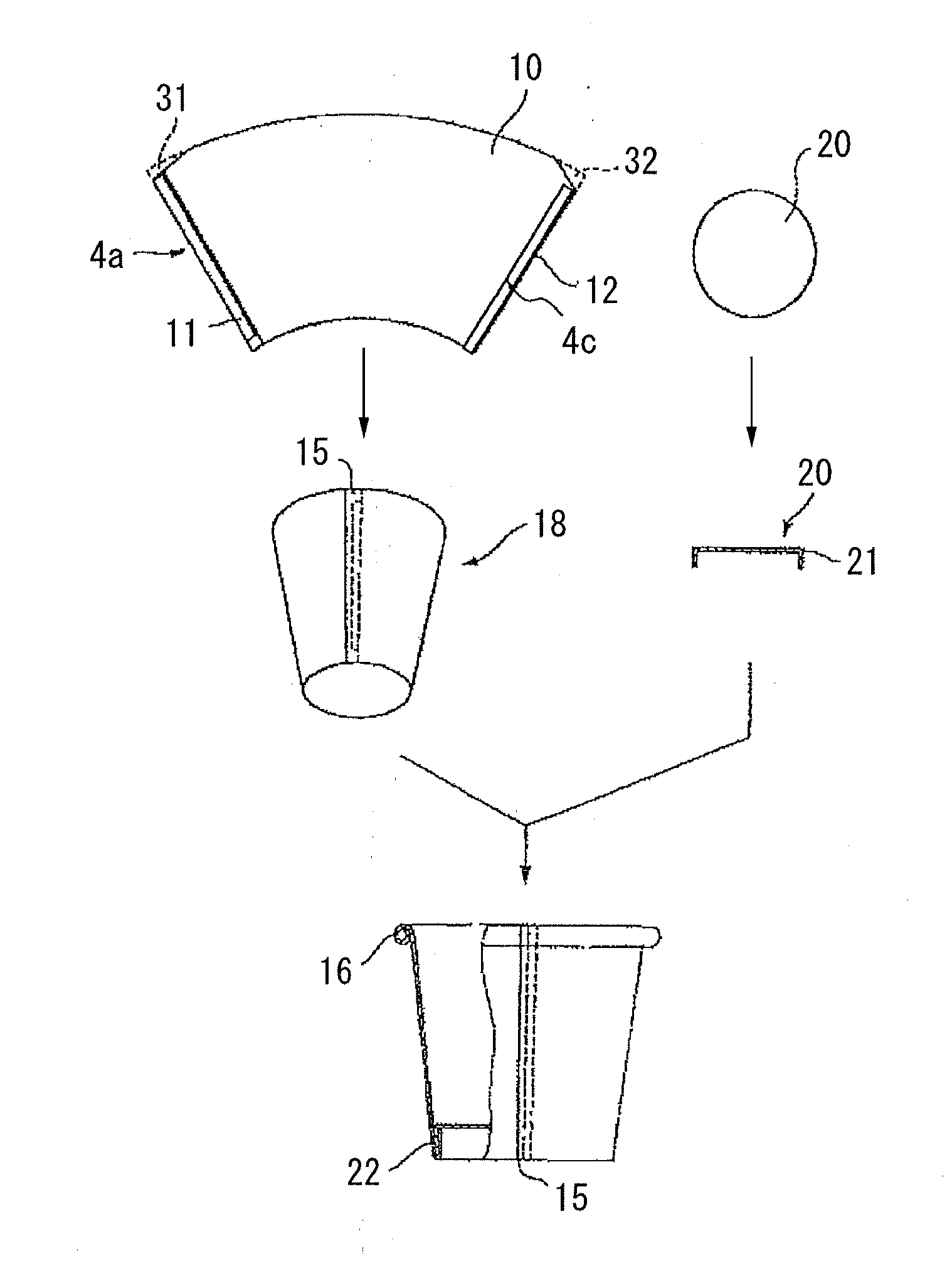
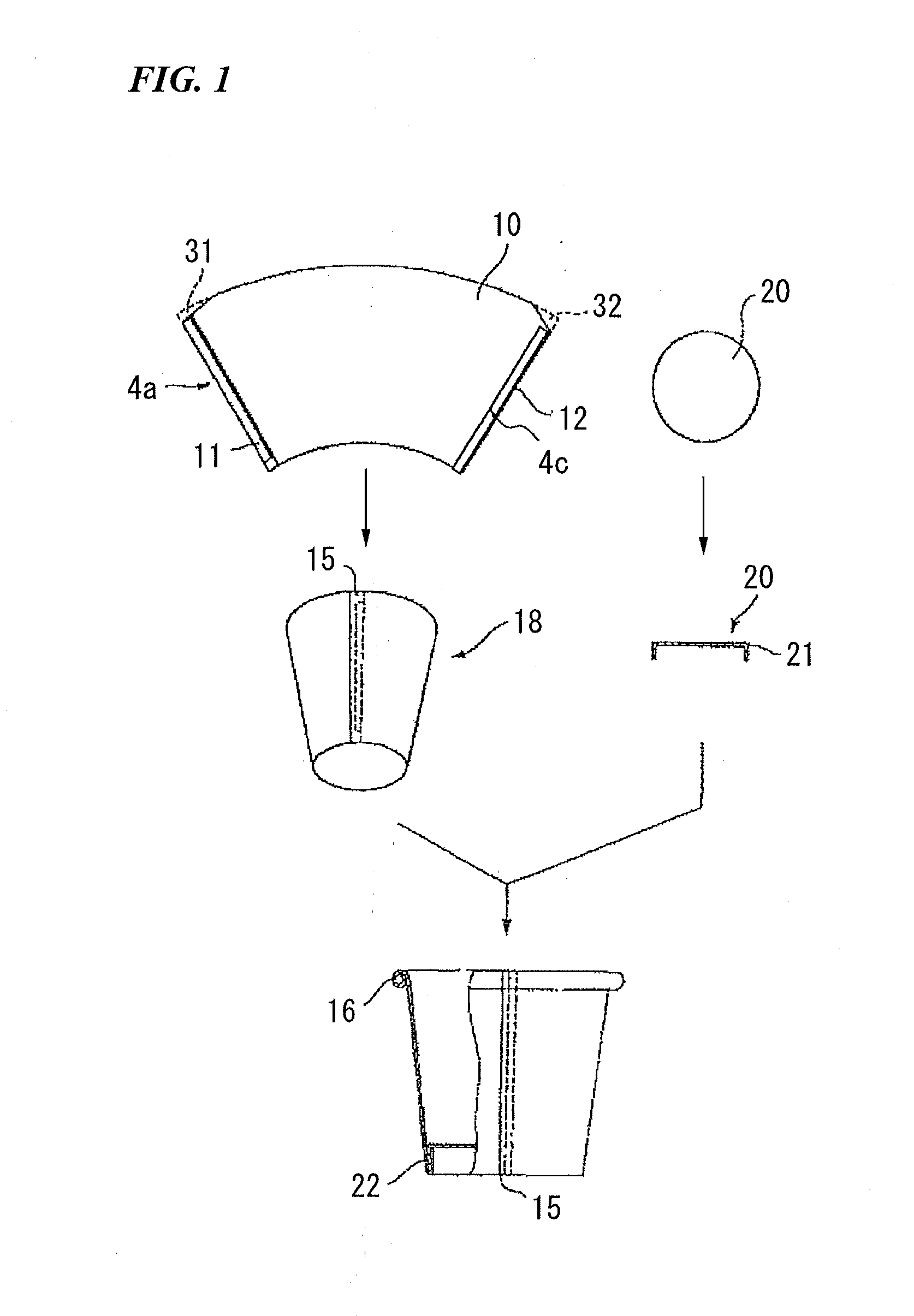
[0147]FIG. 1 is a schematic view showing an example of a manufacturing process of the retort cup related to the present embodiment.

[0148]As shown in FIG. 1, a barrel member 18 is formed in a cylindrical shape which has an attached barrel overlap portion 15. The attached barrel overlap portion 15 is formed such that one end edge 11 of the barrel member blank 10 is overlapped with the other end edge 12. Cutout portions 31 and 32 are respectively provided in upper portions of both lateral end edges of the barrel member blank 10. Additionally, a bottom member 20 has a circular shape and has a peripheral edge portion 21 which is erected downwardly. The outer surface of ...

second embodiment

(2) Second Embodiment

[0193]A cup-like paper container related to a second embodiment of the invention will be described below with reference to the drawings.

[0194]The paper container related to the present embodiment is made up of, for example, a laminated sheet based on paper which has thermoplastic resin layers provided on the inner and outer surfaces thereof.

[0195]FIG. 10 is a schematic view showing a manufacturing process of the cup-like container related to the present embodiment.

[0196]As shown in FIG. 10, a barrel member 218 is formed in a cylindrical shape which has an attached barrel overlap portion 215. The attached barrel overlap portion 215 is formed such that one end edge 211 of the barrel member blank 210 is overlapped with the other end edge 212. Cutout portions 231 and 232 are respectively provided in upper portions of both lateral end edges of the barrel member blank 210. Additionally, a bottom member 220 has a circular shape and has a peripheral edge portion 221 whi...

third embodiment

(3) Third Embodiment

[0249]A retort cup related to a third embodiment of the invention will be described below with reference to the drawings.

[0250]The retort cup related to the present embodiment is made up of, for example, a laminated sheet 403 based on a paper layer 401 which has a thermoplastic resin layer 440 provided at least on the inner surface thereof.

[0251]FIG. 19 is a schematic view showing a manufacturing process of the retort cup related to the present embodiment.

[0252]The retort cup related to the present embodiment is made up of a barrel member 418 and a bottom member 420. The barrel member 418 is formed in a substantially cylindrical shape having an attached barrel overlap portion 415 in which one end edge 411 of the barrel member blank 410 is overlapped with one end edge 412. A cutout portion 431 is provided in an upper portion of a lateral end edge of the barrel member blank 410. The bottom member 420 has a circular shape and has a peripheral edge portion 421 which ...


PUM

PropertyMeasurementUnit
Lengthaaaaaaaaaa
Shapeaaaaaaaaaa
Widthaaaaaaaaaa

Abstract

A retort cup including a tubular barrel portion formed of a barrel portion forming blank having a paper layer and thermoplastic resin layers provided on both surfaces of the paper layer. A bottom portion seals one of the openings of the barrel portion and has a downwardly bent peripheral edge portion. The barrel portion has an attached barrel overlap portion where both end edges of the barrel portion forming blank are overlapped with each other and sealed, a lower fold-back portion is formed at a lower end of the barrel portion and an upper fold-back portion is formed by folding back the ends of the fold-back barrel portion forming blank inwardly. The lower end of the barrel portion, the upper fold-back portion, and the peripheral edge portion of the bottom portion are closely sealed together. The peripheral edge portion is inserted into the lower fold-back portion.

Description

CROSS-REFERENCE TO RELATED APPLICATION[0001]This is the U.S. National Phase Application under 35 U.S.C. §371 of International Patent Application No. PCT / JP2010 / 004091 filed Jun. 18, 2010, which designated the United States and was published in a language other than English, which claims the benefit of Japanese Patent Application No. 2009-148498, filed Jun. 23, 2009, both of them are incorporated by reference herein. The International Application was published in Japanese on Dec. 29, 2010 as WO2010 / 150500 A1 under PCT Article 21(2).TECHNICAL FIELD[0002]The present invention relates to a retort cup structure in which a paper end surface is not exposed to a location contacted by a liquid or the like, and a manufacturing method thereof.BACKGROUND ART[0003]Regarding paper cups which are used after being filled with drinks, such as juice, and for which an upper opening portion is sealed with a lid member, paper cups formed with a joining portion provided to a barrel portion having a blank...

Claims


Application Information

Patent Timeline
IPC IPC(8): B65D6/00B31B3/00B31B50/00
CPCB65D3/14B65D3/22B65D3/28B65D81/3874B31F7/006A42B3/063A47G19/03B01D46/0095
Inventor IYORI, TERUAKIKOTANI, NAOMIUMEYAMA, HIROSHI
Owner TOPPAN PRINTING CO LTD
Learn More