Cage for Radial Needle Bearing, Method for Manufacturing the Same and Radial Needle Bearing

Inactive Publication Date: 2008-09-11
NSK LTD
View PDF0 Cites 9 Cited by
  • Summary
  • Abstract
  • Description
  • Claims
  • Application Information

AI Technical Summary

Benefits of technology

[0043]According to the cage for radial needle bearing, the manufacturing method for the same and the radial needle bearing of the invention which are configured as described above, the shape accuracy of the pair of rim portions and the respective pillar portions can be controlled withou

Problems solved by technology

In the cage for radial needle bearing made of a metal plate which has the construction that has been described heretofore, it has been difficult to realize a good shape accuracy and hence has not necessarily been easy to obtain a good performance.
In additi

Method used


Image

  • Cage for Radial Needle Bearing, Method for Manufacturing the Same and Radial Needle Bearing
  • Cage for Radial Needle Bearing, Method for Manufacturing the Same and Radial Needle Bearing
  • Cage for Radial Needle Bearing, Method for Manufacturing the Same and Radial Needle Bearing

Examples


Example

Embodiment 1

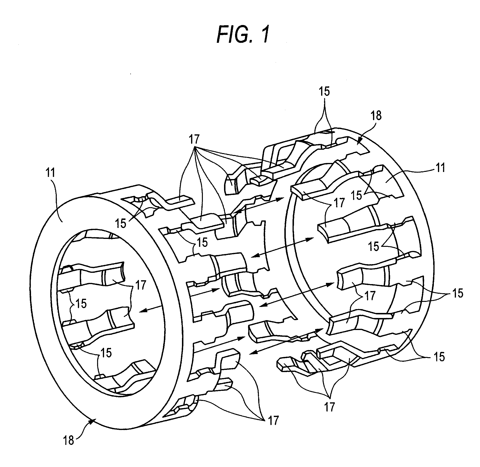
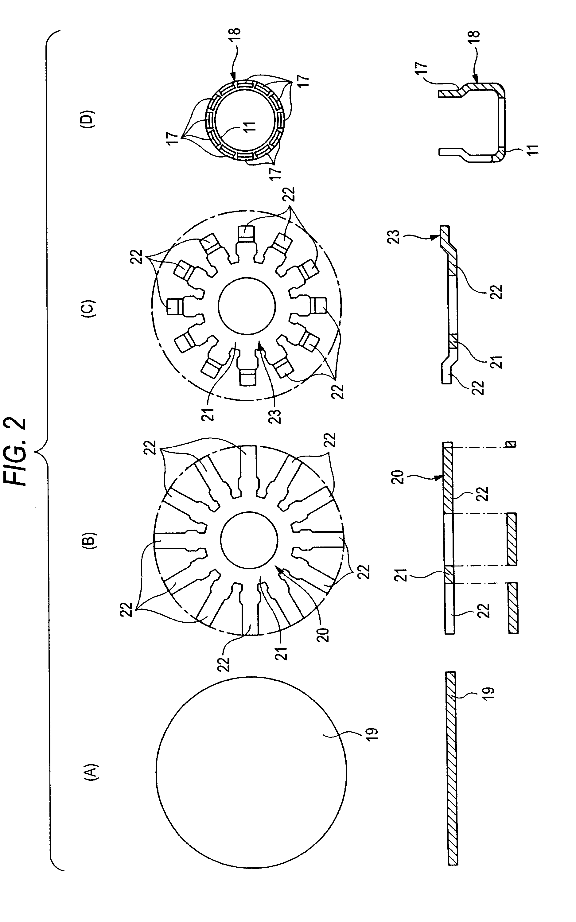
[0159]FIGS. 1 to 2 show Embodiment 1 of the invention. A shape of a cage for radial needle bearing of this embodiment in a completed state becomes substantially similar to that of a conventional construction shown in FIGS. 33 to 35 described above. A difference in shape in the completed state resides only in a sectional shape of respective pillar portions 12, 12 (refer to FIGS. 33 to 35) with respect to an imaginary plane which intersects a center axis at right angles. A feature of this embodiment resides in a point that the respective pillar portions 12, 12 are configured by causing distal end edges of pairs of pillar element portions 17, 17 to butt each other and welding the butted portions. In addition, by adopting the configuration like this, not only the roundness of a pair of rim portions 11, 11 but also shape accuracy and dimension accuracy of respective portions are increased, and the sectional shape of the respective pillar portions 12, 12 with respect to the im...

Example

Embodiment 2

[0170]FIG. 3 shows Embodiment 2 of the invention. In the case of this embodiment, one of distal end edges of respective pillar element portions 17a, 17b whose end portions are connected to each other is made into a concavely curved edge 24, while the other is made into a convexly curved edge 25 which is brought into engagement with the concavely curved edge 24. Radii of curvature of both the concavely curved edge 24 and the convexly curved edge 25 are made the same as each other, so that both the curved edges 24, 25 are brought into close engagement with each other. In addition, with phases of the respective pillar element portions 17a, 17b with respect to a circumferential direction of rim portions 11, 11, (refer to FIG. 1) of a pair of cage elements 18, 18 made to match each other, the distal end edges of the respective pillar element portions 17a, 17b are caused to butt each other, and the butted portion of the respective pillar element portions 17a, 17b is made to be...

Example

Embodiment 3

[0172]FIG. 4 shows Embodiment 3 of the invention. In the case of this embodiment, distal end edges of respective pillar element portions 17c, 17d which make up respective cage elements 18, 18 are made into inclined edges 26a, 26b which are inclined relative to a circumferential direction of rim portions 11, 11 (refer to FIG. 1), respectively. These respective inclined edges 26a, 26b are inclined alternately in opposite directions with respect to the circumferential direction of the rim portions 11, 11 and at the same angle. Then, by causing the distal end edges which are inclined in the same direction to butt each other, the butted portion of the distal end edges of the respective pillar element portions 17c, 17d is welded in such a state that phases of the respective pillar element portions 17c, 17d with respect to the circumferential direction made to match each other.

[0173]Also in the case of this embodiment, by configuring the pillar element portions 17c, 17d in the ...


PUM

PropertyMeasurementUnit
Angleaaaaaaaaaa
Diameteraaaaaaaaaa
Shapeaaaaaaaaaa

Abstract

A cage element 18 in which pillar element portions 17, 17 are made to project from a rim portion 11 is manufactured by performing a punching process and a bending process on a metal plate. With rim portions 11, 11 of a pair of cage elements 18, 18 disposed concentrically with each other and phases in a circumferential direction of the respective pillar element portions 17, 17 made to coincide with each other, distal ends of the respective pillar element portions 17, 17 are butted to each other to be welded together, whereby respective pillar portions are made. The roundness of the respective rim portions 11, 11 and the shape accuracy and interval accuracy of these respective pillar portions are improved without performing troublesome processes, so as to solve the problem.

Description

TECHNICAL FIELD[0001]The present invention relates to a cage for radial needle bearing and an improvement in a manufacturing method for the same and realizes a cage which enables stably obtaining a case with good quality and a manufacturing method for the same.BACKGROUND ART[0002]Radial needle bearings are incorporated in those of rotational support portions of automotive transmissions or various types of mechanical apparatuses portions where a large radial load is applied. For example, in a transmission of planetary gear type which makes up an automotive automatic transmission system, as is known through description in Patent Document No. 1 and the like, a planetary gear is rotationally supported relative to a carrier by a radial needle bearing. FIG. 33 shows an example of a rotational support system for a planetary gear which supports rotationally a planetary gear relative to a carrier like this type. In the case of a structure shown in FIG. 33, both end portions of a support shaf...

Claims


Application Information

Patent Timeline
IPC IPC(8): F16C19/24B21D53/12
CPCB21D53/12Y10T29/49691F16C33/547F16C19/46
Inventor OOTSUKA, KIYOSHIKOBAYASHI, KAZUTOSHINTOU, ISAOHORINO, KEIICHIMIZUSHIMA, YUUKI
Owner NSK LTD
Why Eureka
Try Eureka