Anodic structure and method for manufacturing same

a technology of carbon nanotubes and anodes, applied in the direction of discharge tube main electrodes, nanoinformatics, transportation and packaging, etc., can solve the problems of high manufacturing cost of such an anode structure, high manufacturing cost, and complex manufacturing steps in this process

Inactive Publication Date: 2008-09-11
TSINGHUA UNIV +1
View PDF20 Cites 6 Cited by
  • Summary
  • Abstract
  • Description
  • Claims
  • Application Information

AI Technical Summary

Benefits of technology

[0008]In a present embodiment, a method for manufacturing an anodic structure includes the steps of: providing a carbon nanotube slurry and a glass structure; applying a carbon nanotube slurry layer onto the glass structure; drying the carbon nanotube slurry layer on the glass structure; applying a phosphor layer on the carbon nanotube slurry layer; and solidifying the carbon nanotube slurry layer and the phosphor layer on the glass structure at an approximate temperature of 300˜500° C. and under protection of an inert gas to form the anodic structure.

Problems solved by technology

However, the manufacturing steps in this process are complex, and the materials used in this process are expensive.
Therefore, the manufacturing cost of such an anodic structure is high.

Method used


Image

  • Anodic structure and method for manufacturing same
  • Anodic structure and method for manufacturing same
  • Anodic structure and method for manufacturing same

Examples


Embodiment Construction

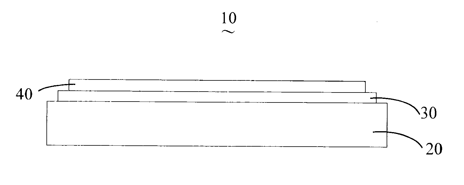
[0015]Reference will now be made to the drawings to describe at least one present embodiment of the anodic structure and the method for manufacturing such.

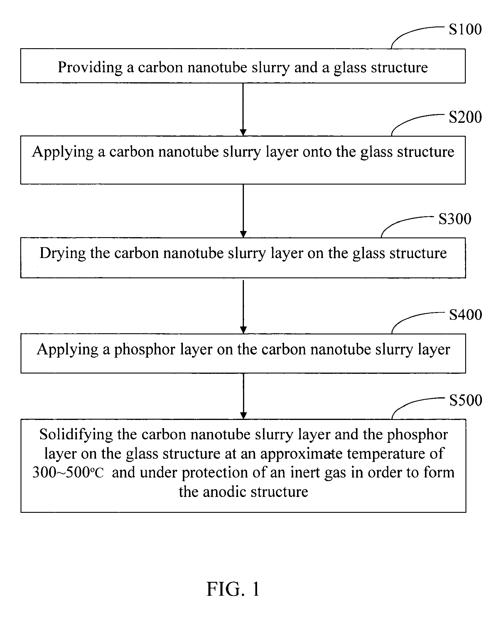
[0016]Referring to FIG. 1, a method for manufacturing an anodic structure, according to a first present embodiment, is shown. The method includes the steps of:

providing a carbon nanotube slurry and a glass structure, shown as step S100;

applying a carbon nanotube slurry layer onto the glass structure, shown as step S200;

drying the carbon nanotube slurry layer on the glass structure, shown as step S300;

applying a phosphor layer on the carbon nanotube slurry layer, shown as step S400; and

solidifying the carbon nanotube slurry layer and the phosphor layer on the glass structure at an approximate temperature of 300˜500° C. and under protection of an inert gas (e.g., N, Ar, He), in order to form the anodic structure, shown as step S500.

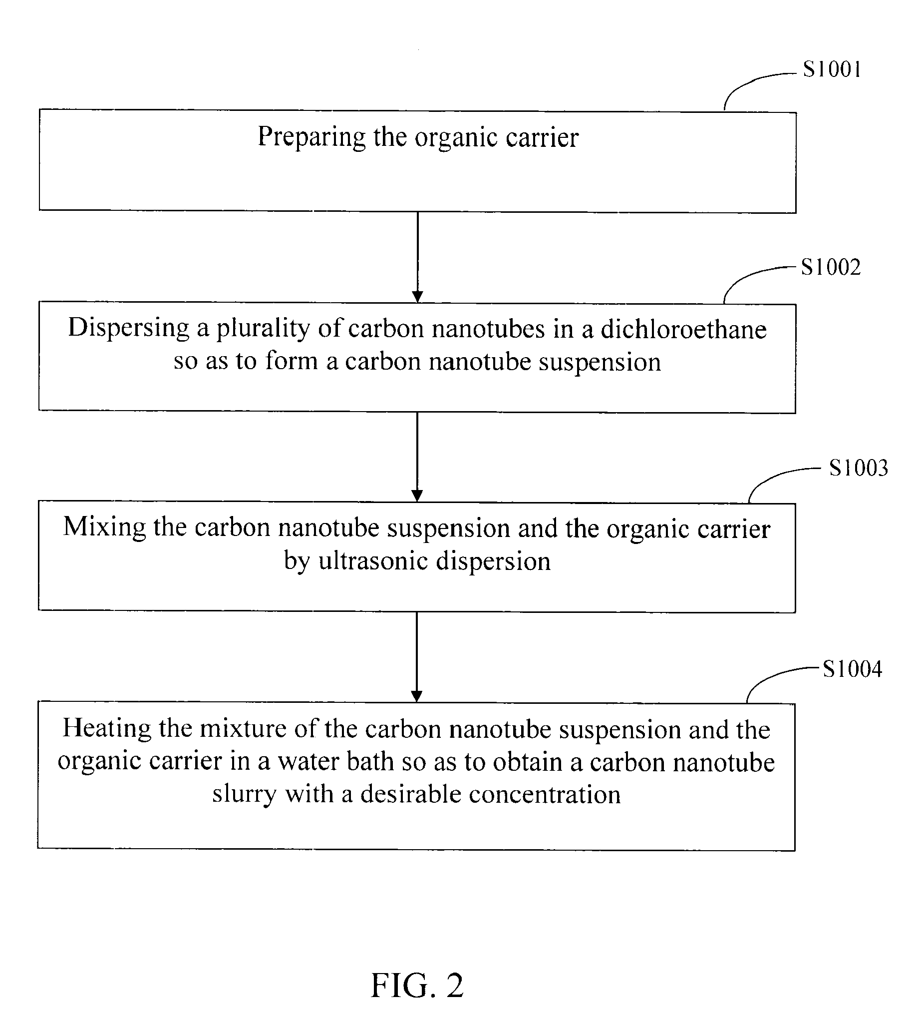
[0017]In step S100, the carbon nanotube slurry typically includes an organic carrier and a plurality o...


PUM

PropertyMeasurementUnit
temperatureaaaaaaaaaa
lengthaaaaaaaaaa
lengthaaaaaaaaaa

Abstract

A method for manufacturing an anodic structure includes the steps of: providing a carbon nanotube slurry and a glass structure; applying a carbon nanotube slurry layer onto the glass structure; drying the carbon nanotube slurry layer on the glass structure; applying a phosphor layer on the carbon nanotube slurry layer; and solidifying the carbon nanotube slurry layer and the phosphor layer on the glass structure at an approximate temperature of 300˜500° C. and under protection of an inert gas to form the anodic structure.

Description

CROSS-REFERENCE TO RELATED APPLICATIONS[0001]This application is related to commonly-assigned, co-pending applications entitled, “Method for Manufacturing Field Emission Electron Source”, filed on Oct. 5, 2007 (Atty. Docket No. US12421), and entitled, “Method for Manufacturing Transparent Conductive Film”, filed on XXXX (Atty. Docket No. US12422). Disclosures of the above-identified applications are incorporated herein by reference.BACKGROUND[0002]1. Field of the Invention[0003]The present invention relates to anodic structures and methods for manufacturing same, and particularly, to an anodic structure with a carbon-nanotube-based film and a method for manufacturing the same.[0004]2. Description of Related Art[0005]Nowadays, anodic structures are used widely in electronic devices, such as cathode ray tube displays, field emission devices, transmission electron microscopes, etc. In the anodic structure, a transparent conductive film is formed on a transparent anodic substrate, and a...

Claims


Application Information

Patent Timeline
Patent Type & Authority Applications(United States)
IPC IPC(8): B05D5/12B32B17/06B32B5/16
CPCB82Y10/00H01J1/38H01J1/53Y10T428/25H01L51/0048H01L51/5206H01J2329/08H10K85/221H10K50/81
Inventor WEI, YANGLIU, LIANGFAN, SHOU-SHAN
Owner TSINGHUA UNIV
Why Eureka
Try Eureka