Method for the automatic calibration of location anchors

a technology of automatic calibration and location anchors, applied in the field of radio location, radio location, item tracking, etc., can solve the problems of difficult to predict the propagation of radio signal variations, difficult to gps type solutions,

Inactive Publication Date: 2008-09-11
HONEYWELL INT INC
View PDF28 Cites 29 Cited by
  • Summary
  • Abstract
  • Description
  • Claims
  • Application Information

AI Technical Summary

Benefits of technology

[0008]It is also an aspect of the embodiments that anchor attenuation values are determined from the anchor received signal strengths and the anchor locations. The distance between each anchor radio is known because the location of each anchor radio is known. The anchor messages can be transmitted with a known strength. As such, the anchor received signal strengths can be used to determine anchor attenuation values. The anchor attenuation values are scaling factors that can correct for environmental factors that effect the propagation of radio signals.
[0009]It is another aspect of the embodiments to receive at least two target receptions. A target can transmit a signal that is received as target receptions by two or more of the anchor radios. As such, there are as many target receptions as there are anchor radios receiving the target transmission. The anchor radios can determine the target received signal strengths of the target receptions.

Problems solved by technology

Other environments, such as inside of buildings, pose difficulties for GPS type solutions.
The local environment, however, causes hard to predict variations in radio signal propagation.

Method used


Image

  • Method for the automatic calibration of location anchors
  • Method for the automatic calibration of location anchors
  • Method for the automatic calibration of location anchors

Examples


Embodiment Construction

[0020]The particular values and configurations discussed in these non-limiting examples can be varied and are cited merely to illustrate at least one embodiment and are not intended to limit the scope thereof. In general, the figures are not to scale.

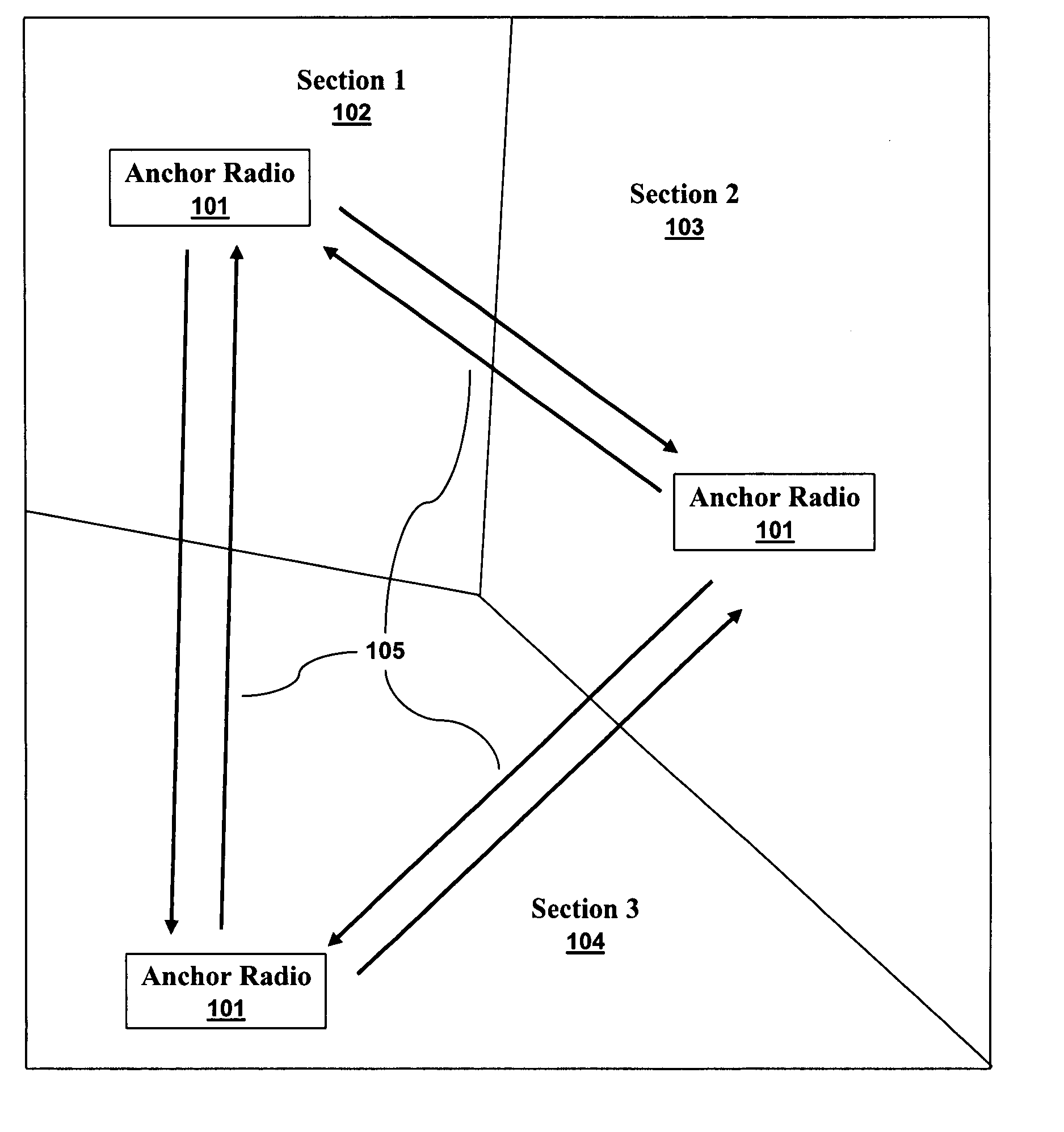
[0021]FIG. 1 illustrates anchor radios 101 exchanging anchor messages 105 in accordance with aspects of the embodiments. Three anchor radios 101 are arranged within an area having three sections. The section 1102 anchor radio 101, the section 2103 anchor radio 101 and the section 3104 anchor radio send and receive anchor messages 105 with the other anchor radios 101.

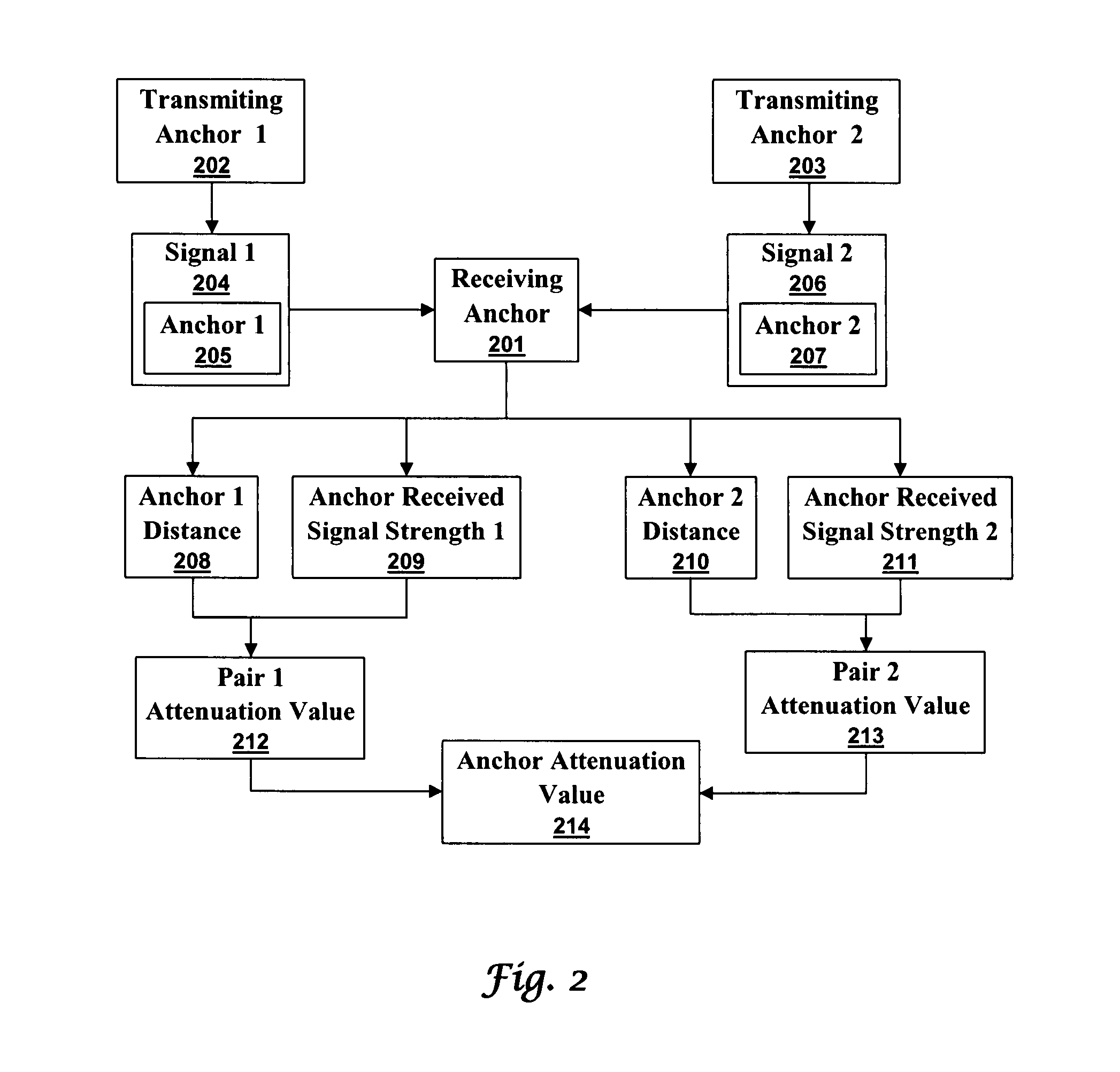
[0022]FIG. 2 illustrates obtaining attenuation values in accordance with aspects of the embodiments. A first anchor radio 202 send a first anchor message, called signal 1204, that is received by a receiving anchor 201. Other anchors can also receive signal 1204. The first anchor message contains an anchor 1 Id 205 so that any receiving radio can examine the message to find w...


PUM


Abstract

A target radio can be located and tracked by an array of anchor radios. The anchor radios are calibrated when each anchor radio transmits an anchor message that is received by the other anchor radios. The distance between anchor radios is known because their positions are known. The received signal strengths are dependent on distance and an attenuation value. The calibration operation uses the received signal strengths and known anchor radio locations to determine the attenuation values of the anchor radios. After calibration, a target radio transmission can be received by the anchor radios. Each anchor radio estimates the distance to the target. The distance estimates and the anchor locations can then be used to determine the target radio's location.

Description

TECHNICAL FIELD[0001]Embodiments relate to radios, radio location, item locating, and item tracking. Embodiments also relate to distance estimation, triangulation, and radio tracking.BACKGROUND OF THE INVENTION[0002]Radios have long been used for locating and tracking people, items, and animals. With the advent of the global positioning system (GPS), tracking and locating within many environments has become much easier. Other environments, such as inside of buildings, pose difficulties for GPS type solutions. Building interiors, furthermore, often require a level of availability and precision that is unavailable from GPS.[0003]Advanced location techniques, such as time-of-flight or time-difference-of-arrival can be used when sufficiently accurate clocks and synchronization are available. Other, less costly techniques use the property that radio signals usually attenuate at a near constant rate over distance. When a signal is transmitted at a known power level a receiving radio can e...

Claims


Application Information

Patent Timeline
Patent Type & Authority Applications(United States)
IPC IPC(8): H04Q7/20H04W36/00
CPCG01S5/0252H04W64/00G01S5/0289G01S5/02213
Inventor HUSETH, STEVE D.BEREZOWSKI, ANDREW G.
Owner HONEYWELL INT INC
Why Eureka
Try Eureka