Fitting and fluid-conveying device connected thereto

a fluid conduit and fitting technology, applied in the direction of hose connection, separation process, application, etc., can solve the problems of increasing complexity, cost and the likelihood of rejecting finished parts, reducing the efficiency of the clamping process, so as to promote a first-order kinetic diffusion reaction and improve the procedure. the effect of speeding up the coupling speed and improving the procedur

Inactive Publication Date: 2008-09-11
PERMA PURE LLC
View PDF38 Cites 62 Cited by
  • Summary
  • Abstract
  • Description
  • Claims
  • Application Information

AI Technical Summary

Benefits of technology

[0012]The fittings described herein can be used in myriad applications that involve tubing, hosing or related fluid conduits, with sizes dictated according to the dimensions of the conduit. Thus, in addition to moisture exchange tubing (such as breathing dryer and humidifier tubes), such fittings can be used for other industrial and fluid-processing equipment, such as sample conditioning systems, thermoelectric coolers, filters, scrubbers and probes connected to the same. Simple water-conveying hoses and associated equipment can also benefit from an appropriately-sized fitting according to the various aspects of the present invention. Likewise, uses for fire and gas detection, environmental control, safety and security equipment and various fluid conveyance applications are also within the scope of the device of the present invention. By extending the length of the clamps along their axial dimension, the fitting can be made to function as a coupler by having both body ends able to be engaged by the clamps, thereby promoting both fluid connectivity and additional resistance to inadvertent tube separation.
[0015]As previously discussed, the water-permeable wall of the tube inner member may be made from Nafion® or a related material that promotes a first order kinetic diffusion reaction. Also as previously discussed, resilient snap-fit features of the fitting clamps allow the fitting to be quickly coupled to a tube. The choice of materials, such as plastic, means the tube and fitting can be a disposable device. This may be particularly beneficial when the apparatus is part of a breathing tube or other medical device, where concerns about sanitary conditions may be paramount. One such use may be in capnography to monitor the concentration or partial pressure of carbon dioxide in respiratory gases, especially during intensive care procedures or such times where anesthesia may be used. During anesthesia, a capnogram provides direct indicia of the elimination of carbon dioxide by the lungs to the anesthesia device, and the device of the present invention can be used to improve such a procedure.

Problems solved by technology

While the overmolded design of FIG. 2 has many benefits, its construction entails numerous steps, which increase complexity, cost and the likelihood of rejected finished parts.
Furthermore, while barbed fittings are common in the industry for connecting tubing for low-pressure applications, where simply inserting a barbed fitting into a tube is sufficient to ensure leak-free connection, their use is limited in situations where higher pressures or resistance to being pulled apart is present.
Unfortunately, separate clamps require additional part tracking and inventorying, and necessitate the use of tools (including pliers, pincers, crimpers, screwdrivers or the like) to connect them to the tube.
Such adds cost and complexity to the clamping process.

Method used


Image

  • Fitting and fluid-conveying device connected thereto
  • Fitting and fluid-conveying device connected thereto
  • Fitting and fluid-conveying device connected thereto

Examples


Embodiment Construction

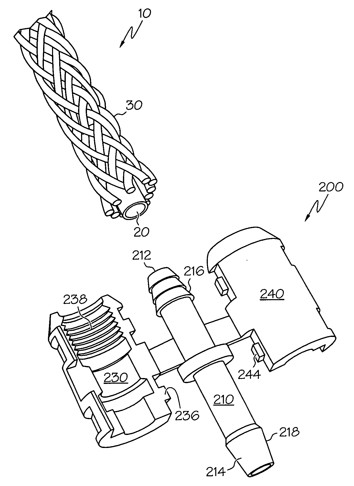
[0026]Referring to FIG. 3, a fitting 200 according to an aspect of the present invention has a body 210 comprising a proximal end 212 and a distal end 214 between which a fluid bore 220 extends to establish fluid communication between a first tube (not presently shown) and a socket, second tube or related receptacle (none of which are shown, and collectively referred to as a second tube, a component, a device or the like, the usage of which will be apparent from the context). A fluid inlet corresponds to the proximal end 212, while a fluid outlet corresponds to the distal end 214, although it will be appreciated by those skilled in the art that the terms “inlet” and “outlet” are relative, and that in the event of a reversal of flow through a first and second fluidly-coupled tubes, the roles would be reversed. Each of the proximal and distal ends 212, 214 include radially-projecting male barbs 216, 218 that act as connectors and can be used to engage complementary surfaces on the res...


PUM

PropertyMeasurementUnit
thickaaaaaaaaaa
thickaaaaaaaaaa
forceaaaaaaaaaa

Abstract

A fitting for a fluid-conveying conduit. The fitting includes integrally-formed clamps that can be used to secure the conduit in a locking relationship so that likelihood of leakage and separation of the fitting and the conduit is reduced. In one form, the fitting and conduit can be used as a moisture exchange device. In a more particular form, the conduit wall of the moisture exchange device includes a water-permeable material such that a humidity level in the conduit can be controlled. Since the fitting is formed separately from the end of the conduit to which it is to be attached, fabrication cost and complexity is reduced.

Description

[0001]This application claims the benefit of U.S. Provisional Application Ser. No. 60 / 893,728, filed Mar. 8, 2007.BACKGROUND OF THE INVENTION[0002]The present invention relates generally to a fitting for a fluid conduit, and specifically to a fitting that is formed separately from the conduit and readily attachable thereto.[0003]Flexible fluid-conveying conduit, such as tubes, hoses or the like, is used in various applications to promote the secure, efficient and leak-free transport and handling of a gas, liquid or combination of both between a fluid source and destination. Examples include tubing used for chemical and related industrial processes, as well as for medical equipment and procedures, many of which require tight controls on the amount of humidity and related moisture present in a fluid flowing through a conduit. Other examples include hoses for water transport, such as garden hoses, potable water supplies or the like. In addition to the aforementioned applications, such ...

Claims


Application Information

Patent Timeline
Patent Type & Authority Applications(United States)
IPC IPC(8): A61B5/097B01D63/06F16L33/18
CPCA61M16/0808A61M16/0816F16L21/06A61M16/1045A61M2230/432A61M16/0875F16L33/23
Inventor SHEVCHUK, GEORGE JOHN
Owner PERMA PURE LLC
Why Eureka
Try Eureka