
Method and system for enhanced fault detection workflow

a fault detection and workflow technology, applied in the field of system status diagnosis, can solve problems such as inability to scale, adversely affect system availability, and performance declin

Inactive Publication Date: 2008-09-11
GENERAL ELECTRIC CO
View PDF24 Cites 26 Cited by
  • Summary
  • Abstract
  • Description
  • Claims
  • Application Information

AI Technical Summary

Benefits of technology

[0007]In accordance with further aspects of the present technique, a detection system is presented. The system includes a workflow module having a workflow manager and configured to determine a working environment, a rule application attribute, or both, where the working environment and the rule application attribute are associated with input data, dynamically optimizing a sequence of operations based on the determined working environment, the determined rule application attr

Problems solved by technology

However, the analysis of the large amount of data in these log files may inordinately lead to delays in fault detection, diagnosis and subsequent servicing of the diagnostic imaging system, and thereby adversely affect system availability.
Unfortunately, use of these presently available techniques for fault detection results in diminished performance.
Furthermore, these techniques are not scalable and hence result in additional setup costs.

Method used


Image

  • Method and system  for enhanced fault detection workflow
  • Method and system  for enhanced fault detection workflow
  • Method and system  for enhanced fault detection workflow

Examples


Embodiment Construction

[0018]As will be described in detail hereinafter, a method for fault detection workflow management and a system for detection configured to optimize a workflow for fault detection and simplify fault detection in a diagnostic imaging system, are presented. Employing the method and system described hereinafter, a generic, scalable, and configurable fault detection workflow framework may be obtained. This fault detection workflow framework may be configured to dramatically enhance fault detection in systems, thereby optimizing the performance of the detection system.

[0019]Although, the exemplary embodiments illustrated hereinafter are described in the context of a medical imaging system, it will be appreciated that use of the diagnostic system in industrial applications are also contemplated in conjunction with the present technique.

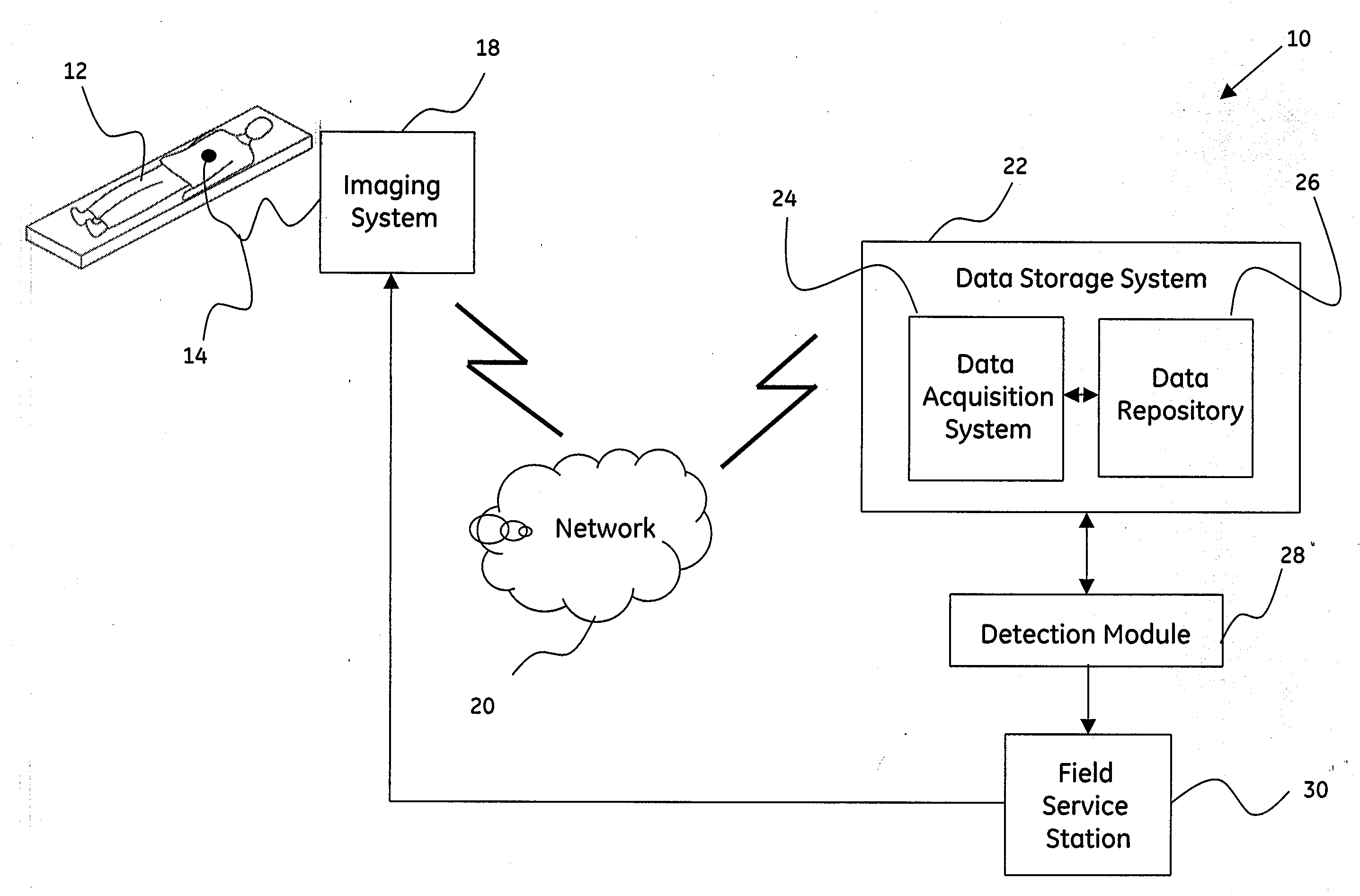
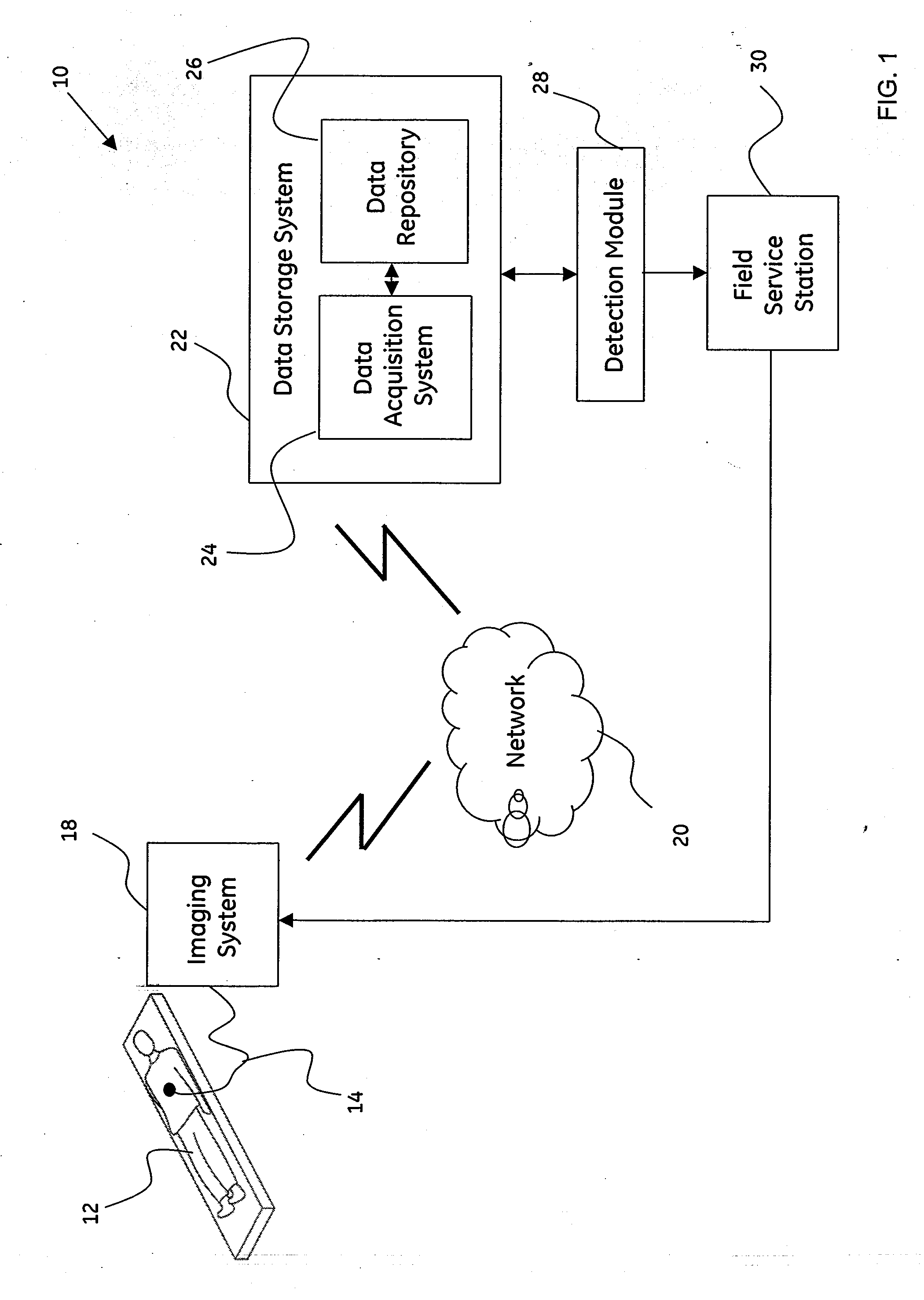
[0020]FIG. 1 is a block diagram of an exemplary system 10 for use in diagnostic imaging in accordance with aspects of the present technique. The system 10 ...


PUM


Abstract

A method for fault detection workflow management is presented. The method includes determining a working environment, a rule application attribute, or both, where the working environment and the rule application attribute are associated with input data. Furthermore, the method includes dynamically optimizing a sequence of operations based on the determined working environment, the determined rule application attribute, or both. Additionally, the method includes processing the input data based on the optimized sequence of operations. Systems and computer-readable medium that afford functionality of the type defined by this method is also contemplated in conjunction with the present technique.

Description

BACKGROUND[0001]The invention relates generally to diagnosis of system status, and more particularly to methods and systems for fault detection.[0002]Diagnostic imaging systems have emerged into an essential aspect of patient care. Medical images that are obtained via the diagnostic imaging sessions have evolved as tools that allow a clinician non-invasive means to view anatomical cross-sections of internal organs, tissues, bones and other anatomical regions of a patient. As will be appreciated, medical images may be obtained from a broad spectrum of imaging modalities, such as, but not limited to computed tomography (CT) imaging, ultrasound imaging, magnetic resonance (MR) imaging, digital mammography, X-ray imaging, nuclear medicine imaging, or positron emission tomography (PET) imaging, or combinations of the above.[0003]As will be appreciated, it is desirable to reduce and / or prevent downtime of the diagnostic imaging systems. Customer satisfaction may be enhanced and maintenanc...

Claims


Application Information

Patent Timeline
IPC IPC(8): G06F11/34
CPCG06F11/2257
Inventor DAMODHARAN, GOPINATH
Owner GENERAL ELECTRIC CO
Learn More