Gas Concentration Measuring Method, Program and Apparatus With Determination of Erroneous Detection

Inactive Publication Date: 2008-09-18
OTSUKA DENSHI CO LTD
View PDF5 Cites 22 Cited by
  • Summary
  • Abstract
  • Description
  • Claims
  • Application Information

AI Technical Summary

Benefits of technology

[0018]Therefore, the gas concentration measuring method according to the present invention may be a method for further finding an absorbance of the sample gas in a wave number region of measurement excluding the wave number region of measurement of the gas to be measured (referred to as “unknown compound absorbance” i

Problems solved by technology

In the methods of multivariate analysis, however, a calculation method becomes very complicated.
The higher the concentration of the interfere

Method used


Image

  • Gas Concentration Measuring Method, Program and Apparatus With Determination of Erroneous Detection
  • Gas Concentration Measuring Method, Program and Apparatus With Determination of Erroneous Detection
  • Gas Concentration Measuring Method, Program and Apparatus With Determination of Erroneous Detection

Examples


Embodiment Construction

[0027]An embodiment of the present invention will be described with reference to the attached drawings.

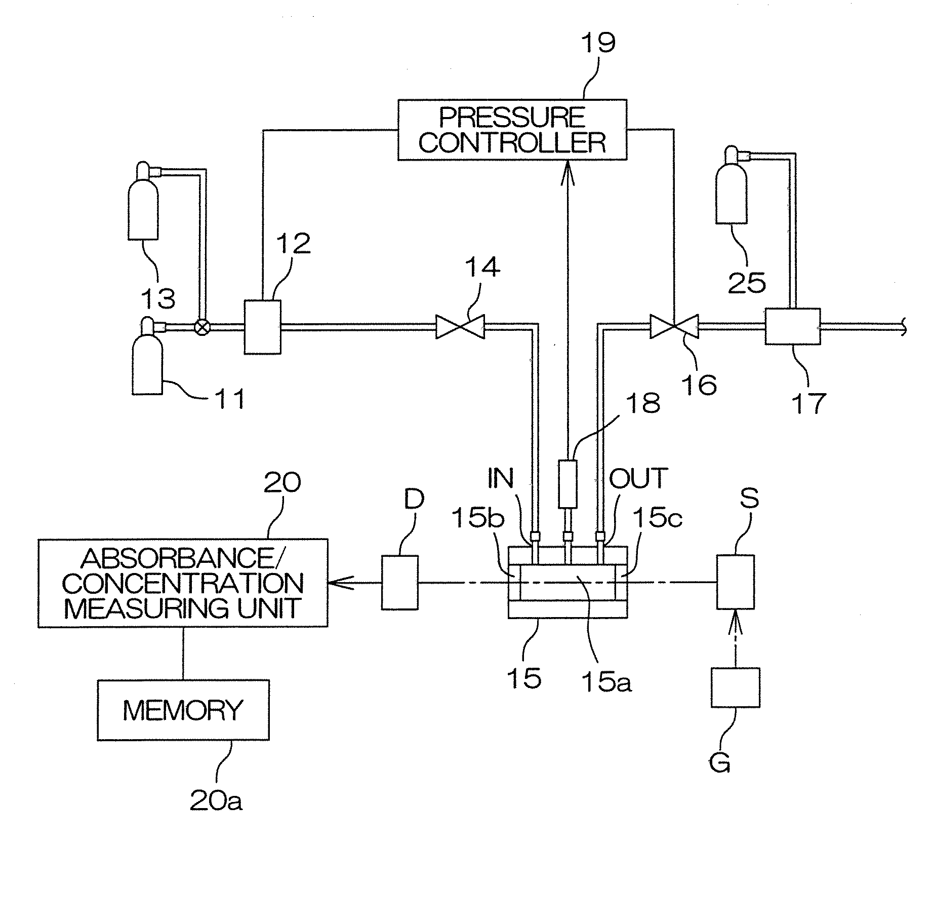
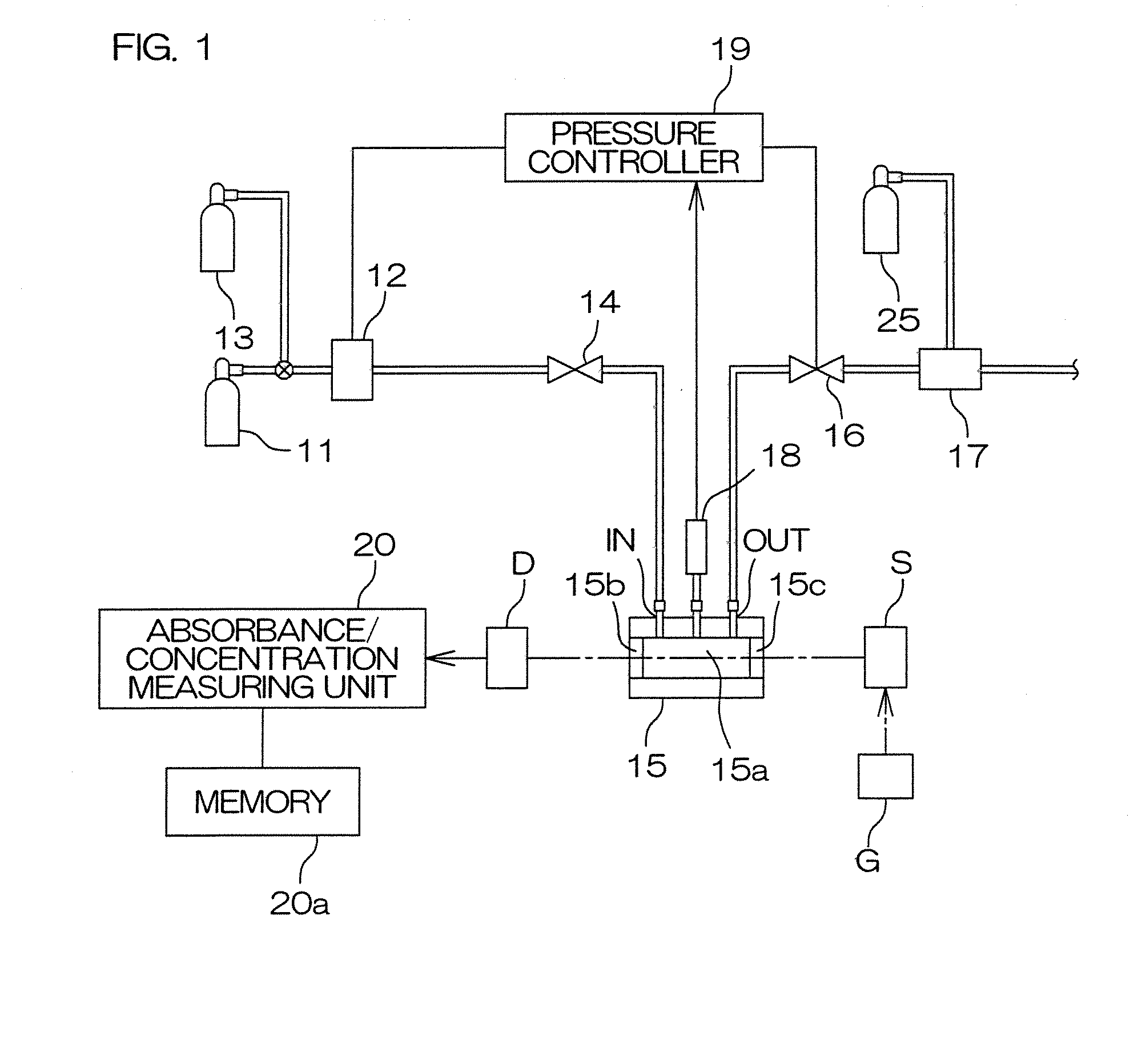
[0028]FIG. 1 is a diagram showing a measuring system for measuring a gas to be measured.

[0029]In FIG. 1, a sample gas cylinder 11 containing a sample gas and a gas cylinder 13 containing a background gas are set in a gas inlet IN of a gas cell 15 through a mass flow controller 12 for adjusting a gas flow rate and an opening / closing valve 14. The sample gas cylinder 11 and the gas cylinder 13 are switched by a valve mounted on each of the gas cylinders 11 and 13.

[0030]On the other hand, an adjusting valve 16 and a vacuum generator 17 (which may be a pressure ejector) for creating negative pressure are connected to a gas output OUT of the gas cell 15. A high-pressure gas cylinder 25 for air, nitrogen, or the like is connected to the vacuum generator 17.

[0031]The gas cell 15 includes a cylindrical cell chamber 15a having a predetermined volume and light transmission windows 15b and 15...


PUM


Abstract

In a wave number region of measurement of a gas to be measured, an absorbance of the gas is found to calculate a concentration thereof, and the concentration is compared with a threshold value (FIG. 3; S8). When the concentration exceeds the threshold value, an absorbance of an interference-component gas is found to calculate a concentration thereof in a wave number region of measurement of the interference-component gas (S9). The concentration of the interference-component gas is compared with a threshold value of the concentration of the interference-component gas (S10) to generate information indicating that the concentration of the gas to be measured is high when the concentration of the interference-component gas is within the threshold value (S11).

Description

BACKGROUND OF THE INVENTION[0001]1. Field of the Invention[0002]The present invention relates to measurement of the concentration of a gas to be measured included in a sample gas.[0003]2. Description of Related Art[0004]A conventionally known gas concentration measuring method will be briefly described. First, the spectrum of light transmitted by a gas having no absorption in a certain wave number region (referred to as a background gas) is acquired to find an integration value B of the amount of the light in the wave number region. Then, the spectrum of light transmitted by a gas to be measured is acquired to find an integration value S of the amount of the light in the wave number region.[0005]The absorbance Abs(S) of the gas to be measured is found using the amount B of the transmitted light by the background gas and the amount S of the transmitted light by the gas to be measured. The absorbance Abs(S) is found by the following equation:Abs(S)=−log(S / B)[0006]When the absorbance i...

Claims


Application Information

Patent Timeline
IPC IPC(8): G01N7/00G01N21/3504G01N21/35
CPCG01N2021/3545G01N21/3504G01N21/5907
Inventor NITTA, SATOSHIOSAWA, YOSHIHIRO
Owner OTSUKA DENSHI CO LTD
Why Eureka
Try Eureka