Pop-up cable electronic marker

a technology of electronic markers and pop-up cables, which is applied in the direction of mechanical actuation of burglar alarms, subaqueous/subterranean adaptions, instruments, etc., can solve the problems of inability to detect any surface instrumentation, inconvenient installation, and inconvenient maintenance and maintenan

Inactive Publication Date: 2008-09-18
MINAROVIC JOE T
View PDF8 Cites 1 Cited by
  • Summary
  • Abstract
  • Description
  • Claims
  • Application Information

AI Technical Summary

Benefits of technology

[0016]It is therefore one object of the present invention to provide an improved electronic marker device for locating an obscured object such as a buried utility.
[0017]It is another object of the present invention to provide such a marker device which can easily be deployed with minimal involvement of field personnel while still placing the transponder at a proper distance from the buried utility.
[0018]It is yet another object of the present invention to provide such a marker device which can be integrated into a preconnectorized cable without adding significant bulk.
[0020]Marker fixtures of the present invention may be pre-installed on a utility infrastructure as part of a factory process. The access points are formed along a conduit and marker fixtures are attached to the conduit at the access points. For cable splices or drops the access points are surrounded by re-enterable closures. The extension member for a marker fixture is loosely secured so that the fixture may be moved around the cable after it has been installed in a trench, to lie atop the access point and be more vertically erect when deployed. The low profile and conforming shape of the pop-up electronic marker fixture make it particularly advantageous for pre-installation on flexible cables that are wound on large reels.

Problems solved by technology

Above-ground marking devices may be installed immediately after the conduit is buried, but they are often lost, stolen, or destroyed after a short period of use.
The primary disadvantage of (non-metallic) warning tapes is that they cannot be detected by any surface instrumentation.
Although the conduit itself may act as a conductor (i.e., when steel pipe or copper wire cabling is used), most conduits are non-conductive and therefore require a trace wire.
There are three significant disadvantages in the use of a trace wire.
Secondly, if a break occurs in the wire (due to excavation, or natural causes such as corrosion, earth movement or burrowing animals), then the wire becomes useless.
Additionally, a receiver cannot distinguish the trace wire from any other conductor in the vicinity.
While passive electronic markers have several advantages over warning tapes and tracing wires, they are still subject to certain limitations relating to, for example, the desired resonant frequency of a particular marker.
One problem associated with using passive or active transponders for remote identification of buried utility structures is that, if the structure is itself metallic (electrically conductive), then it will influence the detection process by causing a variance in the magnetic lines of flux from metallic sources.
This effect can in particular be a problem in marking service drops or splices for a telecommunications cable wherein the cabling has conductive elements or sheaths.
Even with correct placement procedures, movement can occur in a filled ditch or hole as a result of loose unpacked soil, freeze / thaw cycling, water erosion, and other causes.
The marker is located in a raised portion of the closure guard to reduce interference with metallics in the closure, but there are still problems in using that device.
Unfortunately, it is difficult to pre-install markers for a number of reasons.
Markers could be integrated into such factory-made closures but if they were positioned too close to a closure this would result in interference, and if they were positioned distant from the closure the result would be too bulky to be efficiently wound on a reel.

Method used


Image

  • Pop-up cable electronic marker
  • Pop-up cable electronic marker
  • Pop-up cable electronic marker

Examples


Embodiment Construction

)

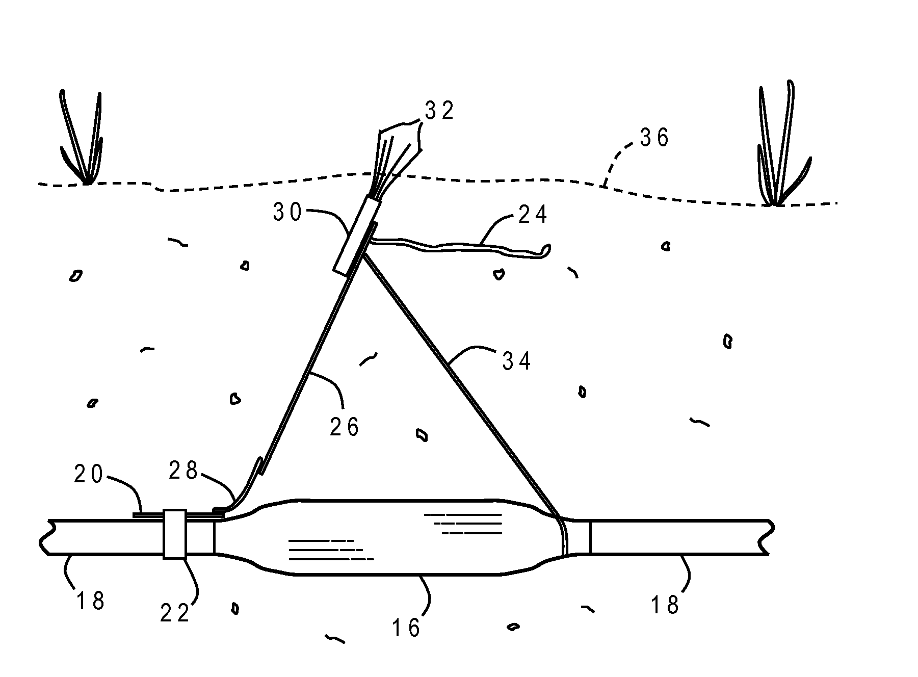
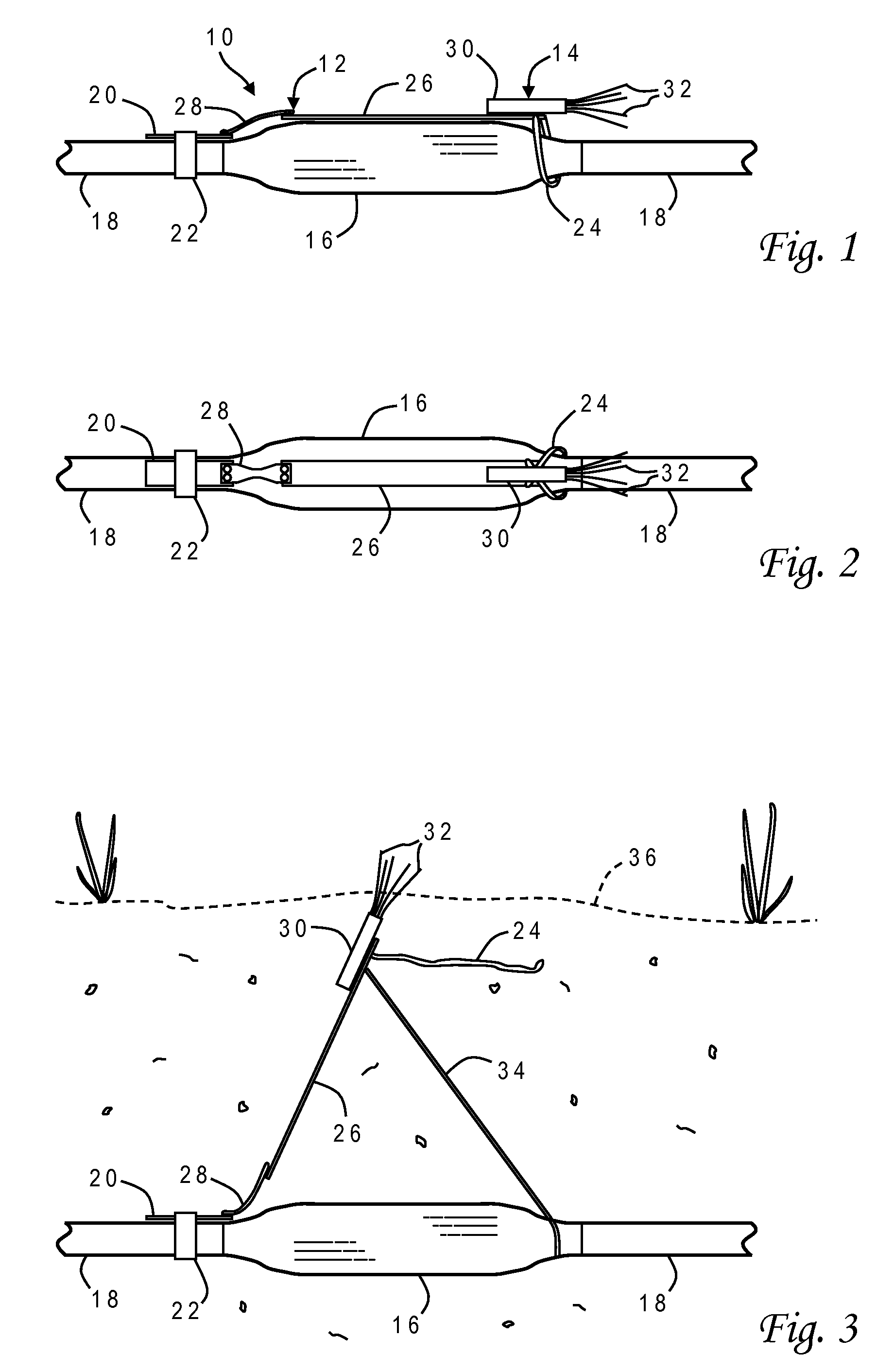
[0028]With reference now to the figures, and in particular with reference to FIGS. 1 and 2, there is depicted one embodiment 10 of a pop-up electronic marker fixture constructed in accordance with the present invention. Pop-up electronic marker fixture 10 is generally comprised of an extension member 12 and an electronic marker 14 affixed to one end of extension member 12. Pop-up electronic marker fixture 10 is shown attached to a cable 18 at a re-enterable closure 16. In this exemplary embodiment, cable 18 is a copper wire or fiber optic telecommunications cable (e.g., for telephone service, cable television or broadband internet access) and closure 16 surrounds an access point of the cable such as a splice or drop.

[0029]Pop-up electronic marker fixture 10 is shown in FIGS. 1 and 2 in a retracted position in which the longitudinal axis of extension member 12 is generally parallel with the longitudinal axis of cable 18 and snugly fits adjacent closure 16. One end of extension membe...


PUM


Abstract

A marker fixture for attachment to a utility conduit such as a telecommunications cable. The fixture has an extension member with an electronic marker at one end, and is secured at the other end to the cable. The extension member is movable between a retracted position wherein the marker is adjacent an access point and an extended position wherein the marker is distant from the access point. The extension member is preferably biased toward the extended position and releasably secured at the marker end proximate the utility structure. The marker fixtures may be pre-installed on a utility infrastructure. The extension member is loosely secured so that the fixture may be moved around the cable after it has been installed in a trench to lie atop the access point. The low profile and conforming shape of the fixture make it particularly advantageous for pre-installation on flexible cables wound on large reels.

Description

BACKGROUND OF THE INVENTION[0001]1. Field of the Invention[0002]The present invention generally relates to devices used to mark and locate obscured objects, and more particularly to an electronic marker device which is attached to a cable closure or other buried conduit.[0003]2. Description of the Related Art[0004]Buried conduits are employed for supplying a wide variety of utilities, including pipelines for gas, water and sewage, and cables for telephone, optical fiber, power and television. It often becomes necessary to locate defective or damaged cables, pipes, etc., in order to repair or replace them. Conversely, it is important to know with as much accuracy as possible the approximate vicinity of such items in order to avoid disturbing them when digging or excavating for other purposes. Above-ground marking devices may be installed immediately after the conduit is buried, but they are often lost, stolen, or destroyed after a short period of use. Therefore, it is common to use u...

Claims


Application Information

Patent Timeline
Patent Type & Authority Applications(United States)
IPC IPC(8): G01D21/00
CPCG01V15/00
Inventor MINAROVIC, JOE T.
Owner MINAROVIC JOE T
Why Eureka
Try Eureka