
Method and apparatus for subsurface anomaly detection and image projection

Inactive Publication Date: 2008-09-18
CANNAMELA JOHN J
View PDF28 Cites 13 Cited by
  • Summary
  • Abstract
  • Description
  • Claims
  • Application Information

AI Technical Summary

Benefits of technology

[0005]Therefore, it is an object of the invention to provide an apparatus and method for rapidly and accurately detecting subsurface anomalies.

Problems solved by technology

This practice presents several problems.
First, the small viewfinders do not permit precise aiming of the camera, particularly in high ambient light conditions.
Second, it is often not possible to locate the exact location of the anomaly, particularly if the surface being examined is large and relatively featureless.
Third, the detection may be of a transient anomaly.
If this is the case it may be difficult to confirm the location of the anomaly later, after having received a report of the results.

Method used


Image

  • Method and apparatus for subsurface anomaly detection and image projection
  • Method and apparatus for subsurface anomaly detection and image projection
  • Method and apparatus for subsurface anomaly detection and image projection

Examples


Embodiment Construction

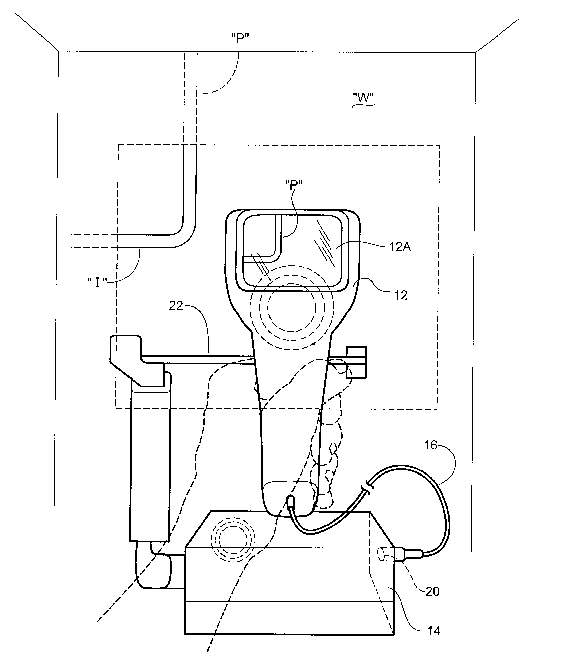
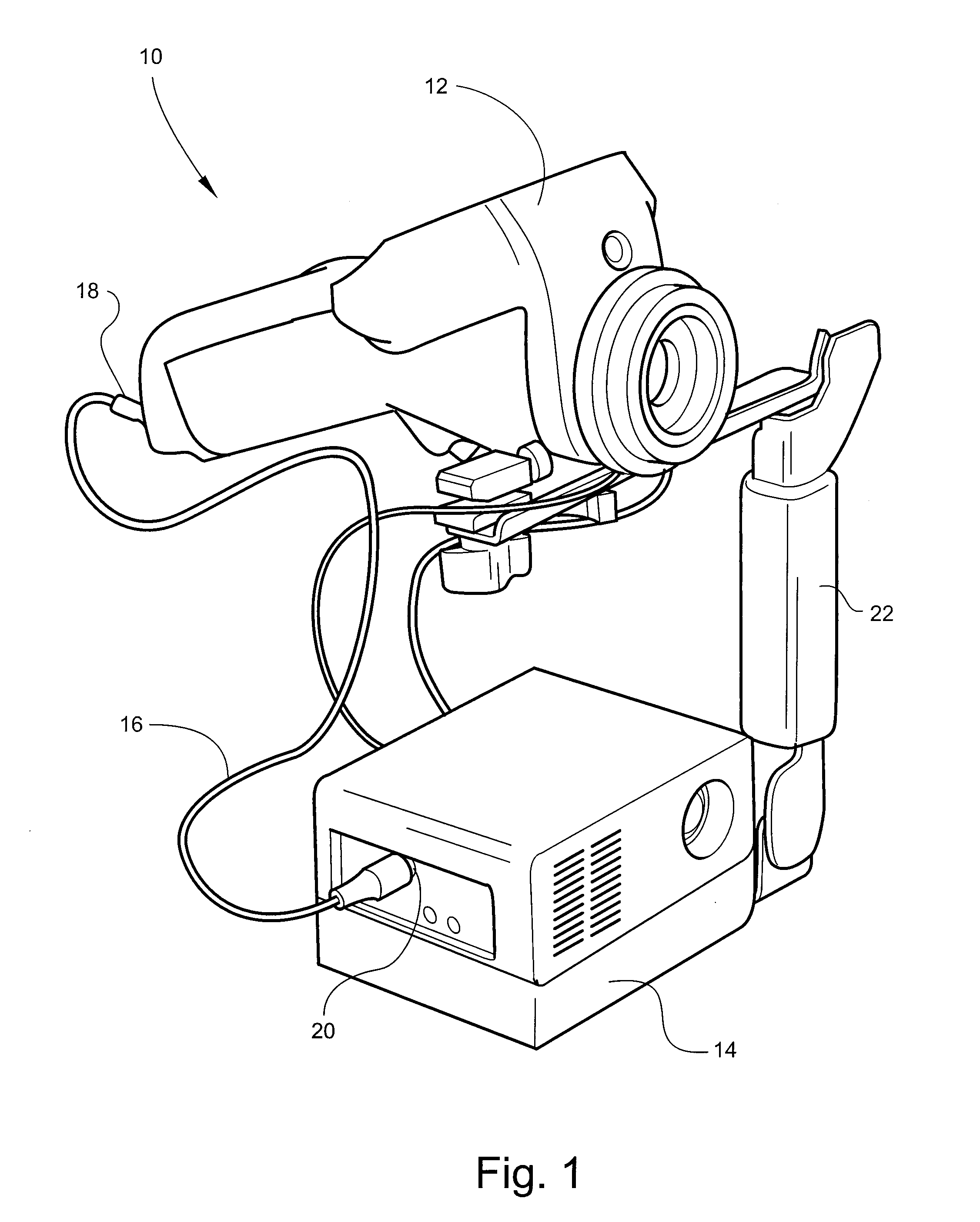
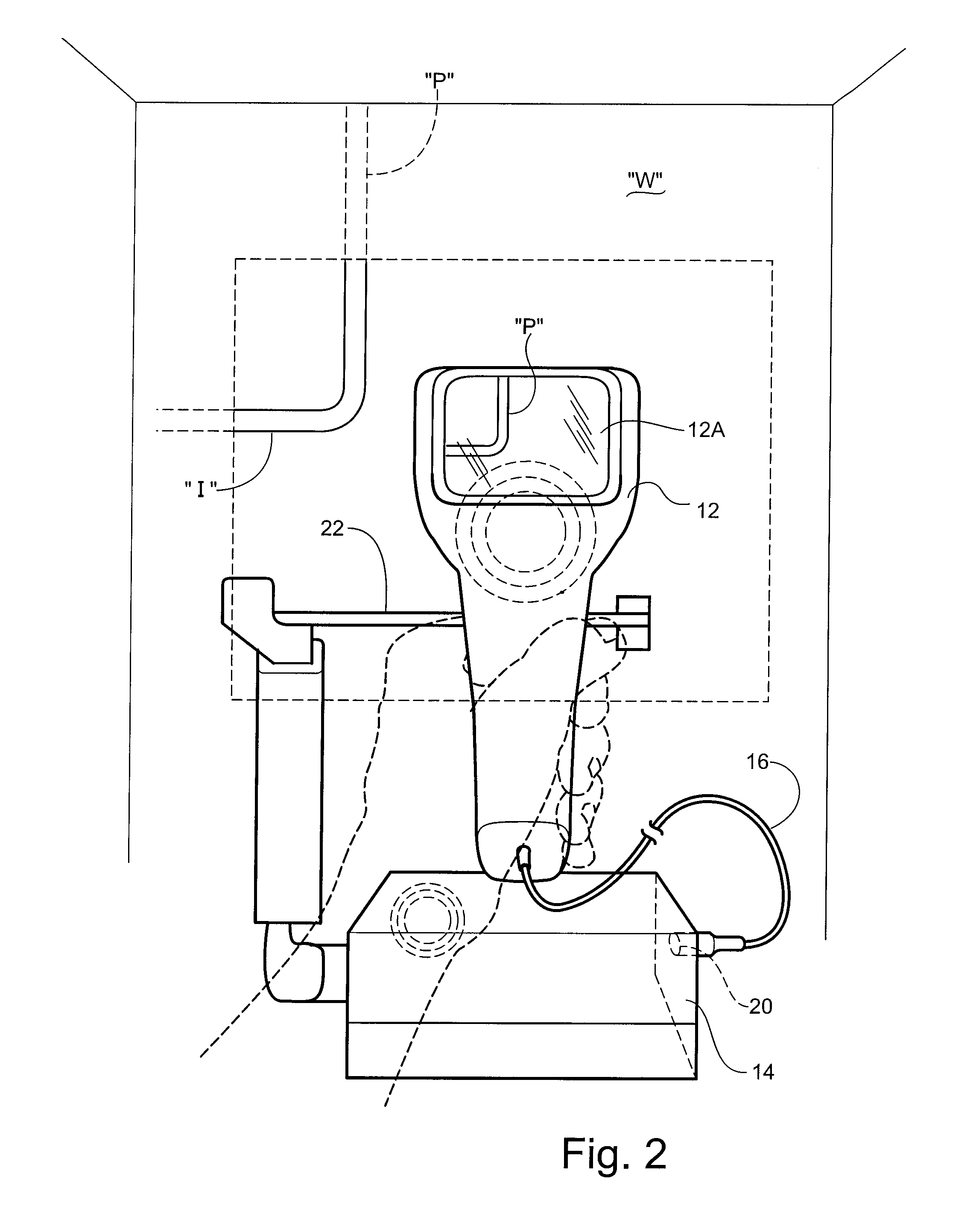
[0026]Referring now specifically to the drawings, an apparatus for detecting subsurface anomalies according to the present invention is shown generally in FIG. 1 at reference numeral 10. The apparatus includes two principal elements, a detector 12 for detecting subsurface anomalies, and a projector 14 for projecting a visual representation of the anomaly onto the surface at the location on the surface behind which the subsurface anomaly is present. The detector 12 may be any type of detector that is capable of detecting subsurface conditions, including IR, UV, ultrasonic or subsonic detection. In the embodiment disclosed herein for purposes of illustration, a IR thermal imaging camera is used, such as a FLIR E-25 thermal infrared camera. This camera is a long wave, handheld focal plane array camera capable of temperature measurement. The camera is capable of storing information for later analysis.

[0027]The detector 12 is connected by a composite video cable 16 from a “video out” por...


PUM


Abstract

A method of detecting subsurface anomalies that includes the steps of utilizing a detector to determine the existence of a subsurface anomaly at a location behind the surface, and generating a signal representative of the anomaly. The signal is transmitted to a projector mounted in image alignment with the detector. The signal is converted into a visual representation of the anomaly; and the visual representation of the anomaly is projected onto the surface at the location on the surface behind which the subsurface anomaly is present. An apparatus for carrying out the method is also disclosed.

Description

TECHNICAL FIELD AND BACKGROUND OF THE INVENTION[0001]This invention relates to a method and apparatus for subsurface anomaly detection and image projection. In particular, the invention relates to a method and apparatus for utilizing, for example, a thermal infrared camera to detect anomalies behind floors, walls, ceilings and in machinery that may be indicative of subsurface conditions such as moisture, overheated areas, malfunctioning machine parts, missing insulation or seals, wall voids, pests and similar other conditions.[0002]Thermal infrared (IR) imaging cameras and similar detectors are known. Typical uses involve detecting the conditions such as set out above. Ordinarily, such cameras store digital data representing any such anomalies in, for example, a PCMCIA card or other memory devices. The images can then be analyzed by computer using software available for this purpose, and reports generated that may include pictures or graphs indicating the general location of the ano...

Claims


Application Information

Patent Timeline
IPC IPC(8): G01N21/84
CPCG01N21/8806G01V9/005G01N25/72
Inventor CANNAMELA, JOHN J.
Owner CANNAMELA JOHN J
Learn More